Page 2-2 Document Ref 947571-001 Rev 2
Site Preparation Quantium 110 & 210 Installation Manual
2 SITE PREPARATION
2.1 General
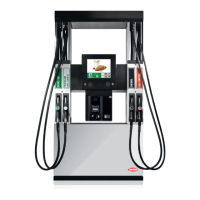
Tokheim dispensers must only be installed on a level island or forecourt surface.
The ground plan will depend on the model ordered. See drawings in Section 3. Refer to
separate LPG Dispenser Manuals for information on LPG dispenser classifications.
VENTILATION
There are no vapour traps in the structure of the dispenser. The hydraulic cabinet is
ventilated via the hydraulic doors. Note : The hydraulic doors must not be blocked
during installation.
VAPOUR BARRIERS
Hazardous areas, as defined in this manual, are applicable only when the dispenser is
located in open air. The control of the hazardous areas in and around the fuel dispenser is
by the use of Vapour Barriers. No specific precautions are taken to reduce the Zone 1
classification of the internal hydraulic housing of the dispenser.
2.1.1 ZONING DIAGRAMS
Quantium 110 and 210 dispensers comply with the requirements of the ATEX
Directive 94/9/EC by conforming to PrEN13617-1.
The classification of vapour barriers are indicated in the following diagrams.
The zone classifications shown are always the highest applicable to that location
within the dispenser. The zone drawings respect the zones created by the use of
vapour recovery systems. No fuel pipes pass through any vapour barrier except
dispensers with Mechanical Registers where a drive shaft passes through the
airgap. Cables glands and blanking plugs used in the vapour barriers are certified
to an equivalent protection rating.