Quantium 110 & 210 Installation Manual Drawings
Document Ref 947571-001 Rev 2 Page 3-5
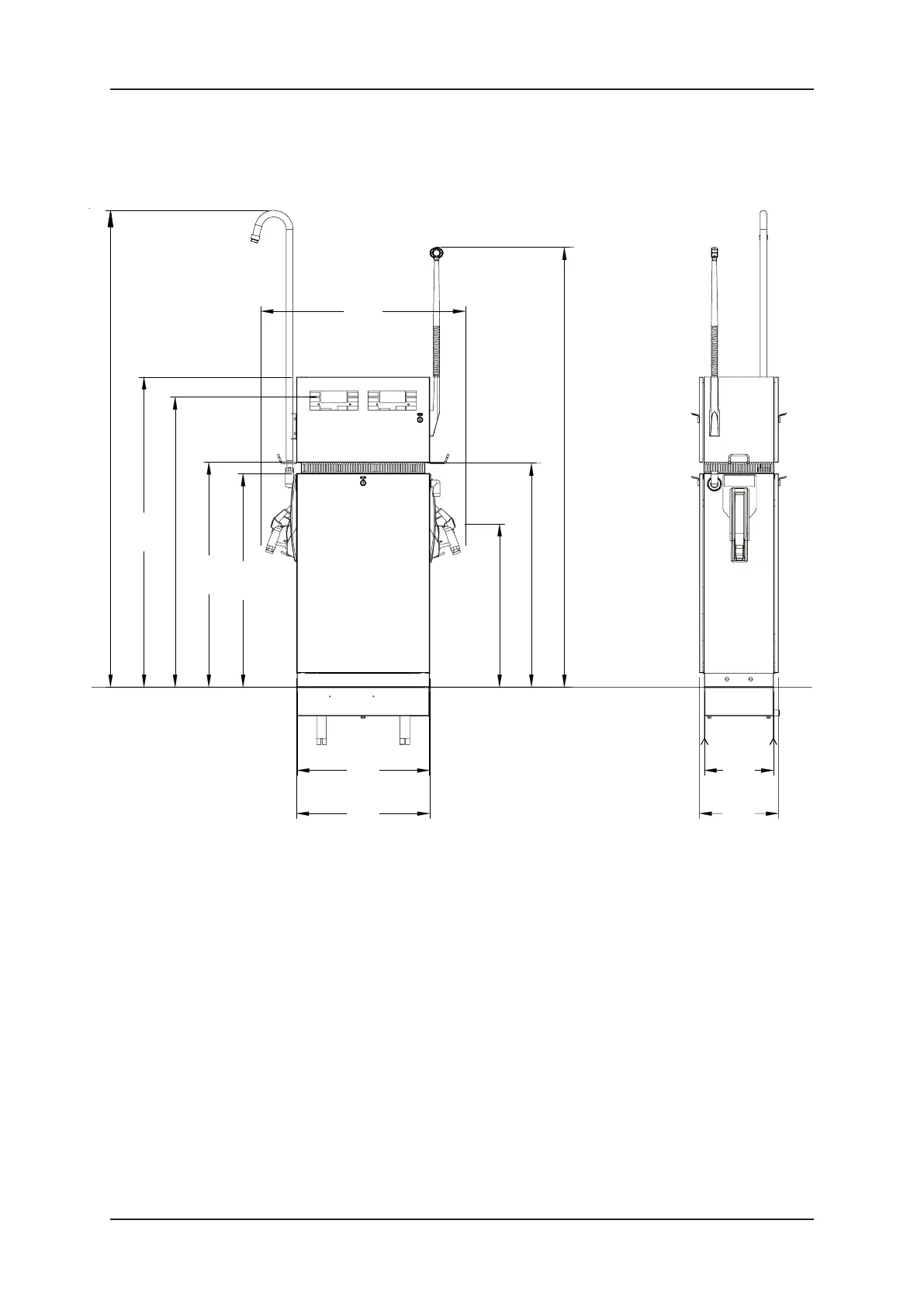
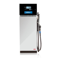
3.2 Q210 Dispenser
3.2.1 Q210 DISPENSER DIMENSIONS
427
350670
673
2410
1137
1032
825
1133
2223
NOTES:-
Side A is the side where the pulleys are (if TQP config).
When facin
Side A the pump pulle
is on the ri
ht hand side
if PASV3 confi
When facin
Side A, filter brackets are on the ri
ht hand side
if submer
ed confi
For option "Display one side only" displays are on side A
Product outlet always on side 2 for single product
Outlet elbows are oriented upwards for sprin
mast and oriented downwards for hose hook
For retainin
hose option, the standard one is with the hook otherwise other options are either
spring or rigid mast.
Side A
(Base)
(Cladding)
Rigid mast
Product 1
Display
Spring mast
Side B
(Cladding)
(Base)
Nozzle
Product 2
Hose Hook
Side A
Island level
1570
1082
1439