Document Ref 947571-001 Rev 2 Page 5-3
Quantium 110 & 210 Installation Manual Installation
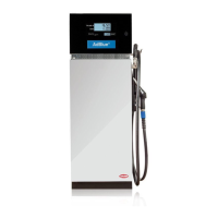
•Side B of the dispenser has the electrical supply (visible upon removal of hydraulic doors).
All single hose models have the hose on the left side when facing side B.
5.3 Lifting
The responsibility for carrying out the procedures described
in this manual lies with the persons lifting and placing the
dispenser.
The installer must supply all lifting equipment and ensure
safe working practice at all times.
Quantium 110 & 210 dispensers can be lifted by forklift
truck under the pallet.
5.4 Placement
Before placement on the island can take place, the following
procedures must be carried out:-
•Check that the electric cabling and piping arrangements have been made in accordance
with the Installation drawing
•Check the pipes have been flushed before connecting the hydraulic components (if
necessary, contact the tank installer)
•Removal of stop plugs on fuel and vapour recovery pipes
•Preparation of mounting frame
•Fitting of seals for cable, fuel and vapour recovery pipe access
•Sealing of non-used holes
IMPORTANT - Make sure Side A of the dispenser is positioned onto the island per
customer specifications. See Section 5.2 for locating Side A.
Lifting equipment can be
hazardous, and must be
rated to lift the weight of
the dispenser. Equipment
could fall and cause
severe injury or death.
Stand clear from the
dispenser when lifting and
lowering.
Side B