44
10. CHECK AND ADJUSTMENTS
■ Checking Calibration
1. Turn on the power for the LS-80X and move into high precision
mode.
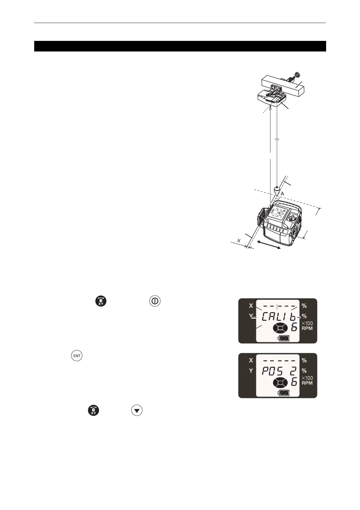
2. Install the LS-80X on a beam 10 meters or higher above the floor,
as shown in the diagram.
3. Hang the plumb bob from the LS-80X indicator to the floor (Point A).
4. Mark the standard line on the floor perpendicular to the direction of
the beam where Point A crosses.
5. Set up the RL-HV for vertical rotation at the position shown in the
diagram and turn on the power.
6. Maintain the level of the standard line on the floor and laser beam,
and move the RL-HV to the direction of the arrow.
Ensure that the laser beam is at the LS-80X indicator position
(check with the buzzer sound from the LS-80X).
7. Measure the difference X between the standard line and laser
beam.
If X is within 1 mm, no adjustment is required. If the difference
exceeds 1 mm, move on to the next adjustment.
■ Vertical calibration and adjustment
1. While pressing the key, press the key.
2. Press the key.
Move the RL-HV in the direction of the arrow to align the standard
line and laser beam.
3. Press either the key or the key to align the laser beam
with the LS-80X indicator position. (check with the buzzer sound
from the LS-80X)
10.2 Vertical Calibration
Beam
Laser beam
Standard line
Level sensor
Approx.
10cm
Approx. 10m
 Loading...