Do you have a question about the Topcon RL-VH3A and is the answer not in the manual?
Guidance on protecting the instrument from severe vibration or impact during transport.
Details on potential interference from reflective surfaces and how to mitigate it.
Explanation of the meaning of WARNING symbols and their potential consequences.
Explanation of the meaning of CAUTION symbols and their potential consequences.
Covers risks of fire, electric shock, physical harm, and laser beam hazards.
Lists specific precautions related to avoiding hazards and damage to the instrument.
Instructions on wearing protective clothing during operation.
Legal disclaimer outlining manufacturer's limitations of liability.
Details on product classification as Class 3A and adherence to safety standards.
Identifies labels indicating laser emission points and required avoidance of exposure.
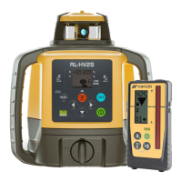
Lists all standard components included in the RL-VH3G/A/B package.
Details the different types of battery configurations available for the instrument.
Explains how visible beam lasers aid work and the 90° angle emission.
Highlights the bottom beam feature for precise centering without plumb bobs.
Describes the automatic and manual focusing capabilities for specific models.
Explains the laser beam's automatic search and tracking function for targets.
Details the 'drawn' scan feature for hands-free operation up to 180°.
How to automatically align the laser beam to a target point.
Procedure for automatically setting grades using an alignment target.
Enables a plumb laser spot for initial laser setup over a control point.
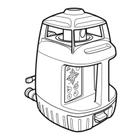
Identifies and labels the main parts of the RL-VH3G/A/B rotating laser.
Illustrates and names wall mount models and magnetic scanning targets.
Describes the alignment target, noting color differences for specific models.
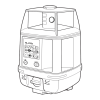
Details the buttons and indicators on the control panel for the RL-VH3A model.
Details the buttons and indicators on the control panel for the RL-VH3B model.
Details the buttons and indicators on the control panel for the RL-VH3G model.
Explains the functionality of the Y2, Y1, X2, and X1 arrow keys for various modes.
Instructions for installing batteries into the instrument.
Steps for setting up the instrument for horizontal rotation.
Procedure for setting up the instrument for vertical rotation.
Instructions for using the plumb beam feature for centering.
Explanation of the battery warning indicator signals and their meaning.
Describes the meaning of the auto-leveling lamp states (flashing, solid ON).
Instructions on how to turn off the auto-leveling function and enter manual mode.
How to use the scanning mode to track a magnetic scanning target.
Procedure for 'drawn' scan and hands-free operation using a target.
Details automatic and manual focusing for specific models using the focus key.
How to change the rotation speed using the speed control pads.
Using the laser pointing mode to stop rotation and manually point the beam.
Using an optional electronic laser sensor for long range or outdoor applications.
Enables a plumb laser spot for initial laser setup over a control point.
Function to prevent operation if the instrument is disturbed, ensuring accuracy.
Details the high power mode for the RL-VH3G model and its limitations.
How to electronically set slopes in X, Y, or both axes (compound slope).
Step-by-step guide to setting automatic grade using an alignment target.
Procedure for setting up a dual axis slope using alignment target and key presses.
How to return the instrument to auto-leveling mode after setting slopes.
Information on operating range errors for slope settings and error indication.
Procedure for manually setting up slopes using arrow keys.
Steps for vertical setup using the plumb finder mode and control point.
How to perform auto line control using the instrument's control panel.
Instructions for making precise adjustments to the laser beam after alignment.
Procedure for auto line control using the alignment target side.
Information on operating range errors for line control and how to reset.
Steps for manually adjusting the beam position after initial alignment.
How to manually align the laser beam without an alignment target.
Details operating range errors for manual line control and error cancellation.
Step-by-step guide to setting up 90° vertical layouts using the instrument.
Instructions for removing and replacing dry cell batteries in the instrument.
Procedure for installing the rechargeable battery pack into the holder.
Steps for charging the rechargeable battery using the AC/DC converter.
Important notes regarding charging, storage, and usage of batteries.
Instructions for applying calibration decals to the instrument's control panel.
Steps to check the horizontal calibration accuracy of the instrument.
Procedure to adjust the horizontal calibration if it falls outside acceptable limits.
Detailed steps for performing and confirming horizontal calibration adjustments.
Procedure to check for and identify horizontal rotation cone errors.
Guidance on contacting a dealer if a horizontal rotation cone error is detected.
Steps to check the upward vertical calibration for RL-VH3G/A models.
Detailed measurements for confirming upward vertical calibration accuracy.
Steps to check the upward vertical calibration for RL-VH3B models.
Detailed measurements for confirming upward vertical calibration accuracy for RL-VH3B.
Procedure to adjust vertical calibration for RL-VH3A/B/G models.
Additional notes for vertical calibration adjustment on RL-VH3G/A models.
Procedure to check the accuracy of the downward laser beam.
Guidelines for cleaning and storing the instrument properly.
Details on the Wall mount-2C accessory for attaching the instrument to walls.
Instructions on how to attach and detach the instrument from mounts.
Description of Wall mount model-1C and laser sensor holder model 5.
Information about the clip-on target accessory for gripping girders or ceilings.
Overview of the LS-70A and LS-70B laser sensors, including controls and functions.
Explanation of the auto-cut off feature for the laser sensors.
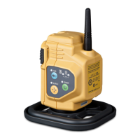
Description of the buttons and operational controls on the RC-30 remote.
Detailed explanation of each function available on the RC-30 remote control.
Procedure to set the same communication channel on the instrument and remote.
Details accuracy parameters for upright and laydown instrument configurations.
Specifications for rotation speeds, scanning width, and line control.
Specifications for slope setting accuracy, range, and plumb finder accuracy.
Details continuous operating times, dimensions, and weights of the instruments.
Table showing visible beam width and diameter at various distances.
Specifies the datum laser position for upright and laydown instrument setups.
Table explaining LED indicators and their corresponding errors.
Provides countermeasures for various error conditions indicated by LEDs.
| Type | Rotary Laser Level |
|---|---|
| Self-Leveling Range | ±5° |
| Laser Class | Class 2 |
| Waterproof/Dustproof | Yes |
| IP Rating | IP66 |
| Range | 800 m (diameter) with receiver |
| Leveling Method | Self-leveling |
| Power Source | Rechargeable battery pack |
| Rotation Speed | 600 RPM |
| Laser Diode | 635 nm |
| Operating Temperature | -4°F to +122°F |