Installation
Antenna Installation
35
SRL-35 Operator’s Manual P/N: 1003224-01
Antennas must be installed well away from metallic objects. In the case of small antennas this distance
should be at least ½ m. With large antennas the distance should be >5 m and in case of repeater antenna
combinations >10 m.
If the system contains a large number of radio modems, the best location for an antenna is the highest point
of a building and possibly an additional antenna mast. If a separate antenna mast is used, the antenna can,
if necessary, be installed sideways about 2…3 m from the mast itself.
When installing an antenna possible interference sources must be considered. Such interference sources
are, for example:
•
mobile telephone network base station antennas
•
public telephone network base station antennas
•
television broadcast antennas
•
radio relay antennas
•
other radio modem systems
•
PC-related devices (approximately 5 m radius from antenna)
When ordering antennas we request you to note that antennas are always tuned to a specific frequency
range. Simple antennas and antennas, which have been constructed of stacked yagi-antennas, are typically
rather broadband. As the number of yagi-elements increases the frequency range becomes narrower. Note
this specially with 35W.
When designing and installing a system it is advisable to prepare to test the system, and also to consider
serviceability of the system. In particular cabling should be planned to allow easy access and to allow for
maintenance. It is often practical to use long antenna cables, so that the radio modem can be installed far
enough from the antenna itself to a location that is easily accessible (see section 10).
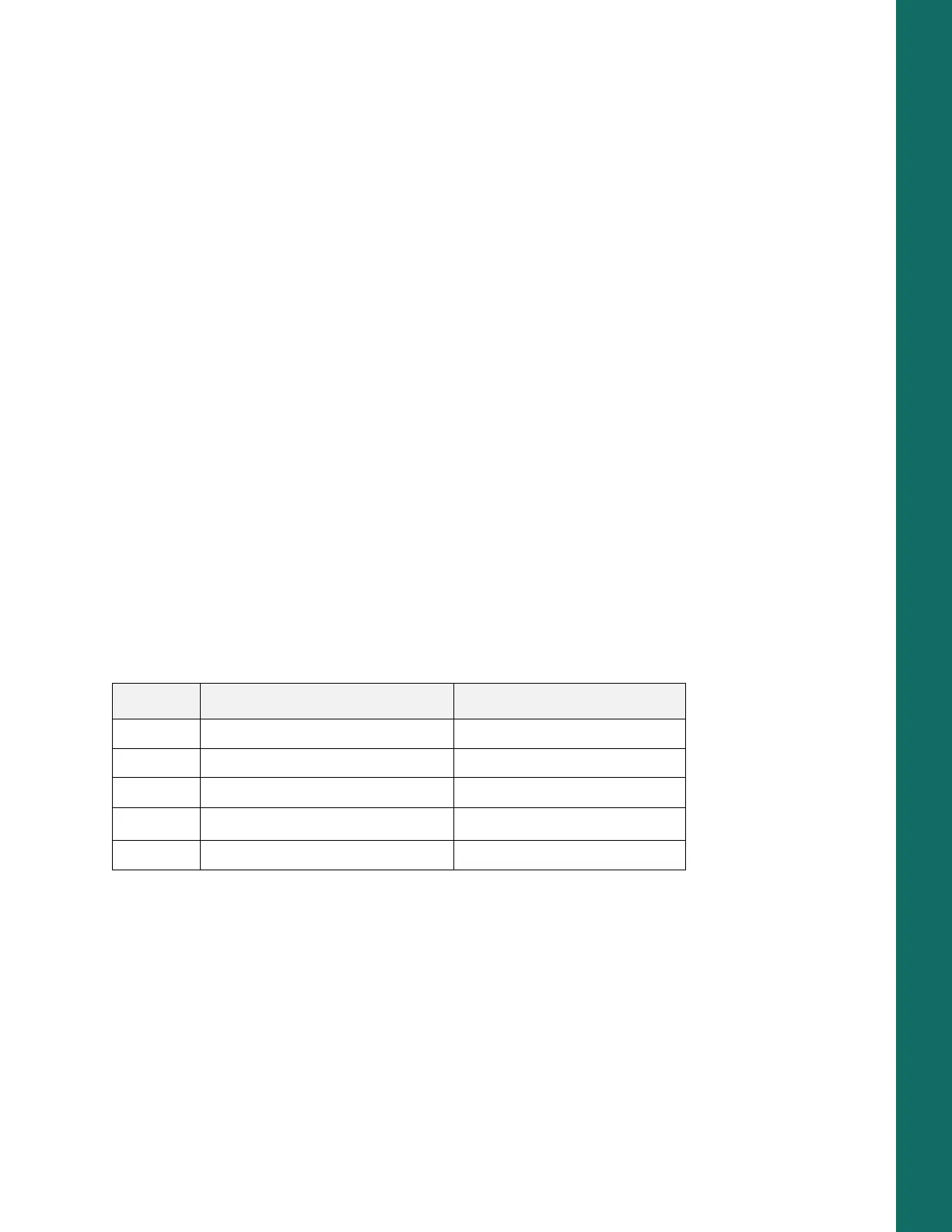
The type of the antenna cable is dependent on the length of the antenna cable, and the following table can
be used to select a suitable type:
If there is a line-of-sight path between the antennas a 6 dB power marginal is usually adequate. However,
if the connection is built on the reflection and/or the knife-edge diffraction the path loss can vary even 20
dB depending on the weather conditions. In this case a short test can give a too positive result of the quality
of the connection. Thus the height of the antennas and topographical obstacles must be surveyed with
great care. From time to time a marginal connection can be used if the data transmission protocol is well
prepared for this and the data transmission that occasionally slows down does not cause any problems to
the system.
Vertical polarized antennas (antenna elements are in vertical position) are often used in radio systems. In
a system between a base station and substations vertical polarization is recommended. The radio modem
antenna cannot be mounted on the same level as the other substation antennas in the same building. The
Table 17. Antenna Cables
Length Type Attenuation 10m/450MHz
<5m RG58 3.0dB
0…20m RG213 1.6dB
>20m ECOFLEX10 0.9dB
>20m AIRCOM+
0.8dB
a
a. AIRCOM+ cable is partially air insulated, so the use of this cable requires that the
connection between the cable and the connectors are fully airtight.
>20m ECOFLEX15 0.6dB