Specifications
Connectors
47
SRL-35 Operator’s Manual P/N: 1003224-01
Connectors
The device contains a data, power and antenna connector.
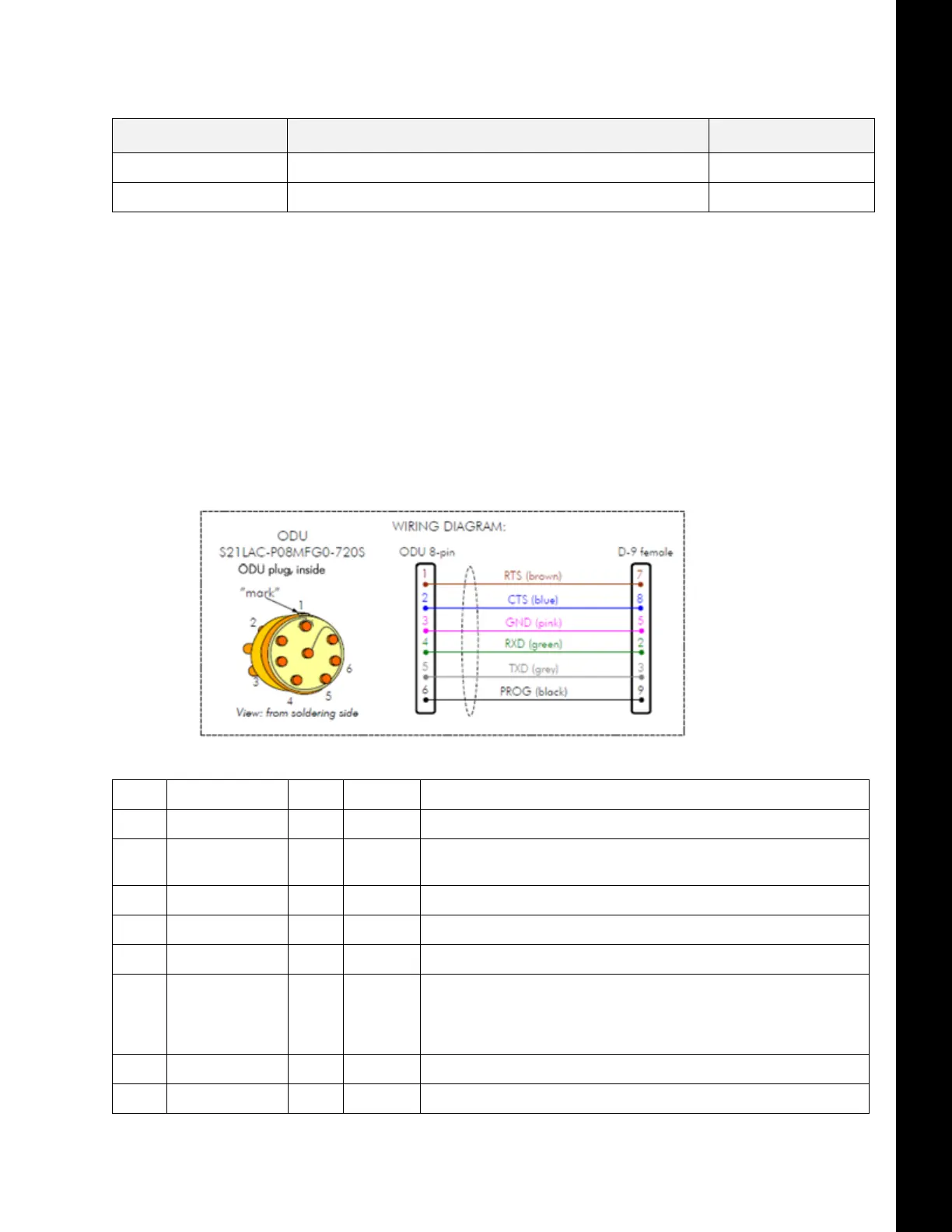
Data Connector
The device adopts a high standard waterproof ODU 8-pin data connector.
•
DTE is an abbreviation for Data Terminal Equipment
•
I/O column below denotes the direction of the signal
•
“IN” is from DTE to the radio modem, “OUT” is from the radio modem to DTE
Table 23. Measurements
OTHER MEASUREMENTS
ESD-failure threshold 8 kV contact, 15 kV air discharge
Immunity test 10V/m
Table 24. Data Connector
PIN NAME I/O LEVEL EXPLANATION
1 RTS IN RS-232 Request To Send from DTE
2 CTS OUT RS-232 Clear To Send. This signal indicates that the radio modem's serial interface is
ready to receive data from DTE.
3 SGND - - Signal ground
4 RX OUT RS-232 Receive Data to DTE from the radio modem
5 TX IN RS-232 Transmit Data from DTE to the radio modem
6 MODE
(DATA/PROG)
IN
0 - 1 6 V <1VDC or connected to ground = Programming Mode
>3VDC or Not connected = Data Transfer Mode Note
a
a. Programming Mode is for changing the settings of the radio modem via Programming menu. Normally the MODE line is NOT connected
i.e. the radio modem is in Data Transfer Mode.
7 Not connected
8 Not connected