2.3.2 Reference Schematics
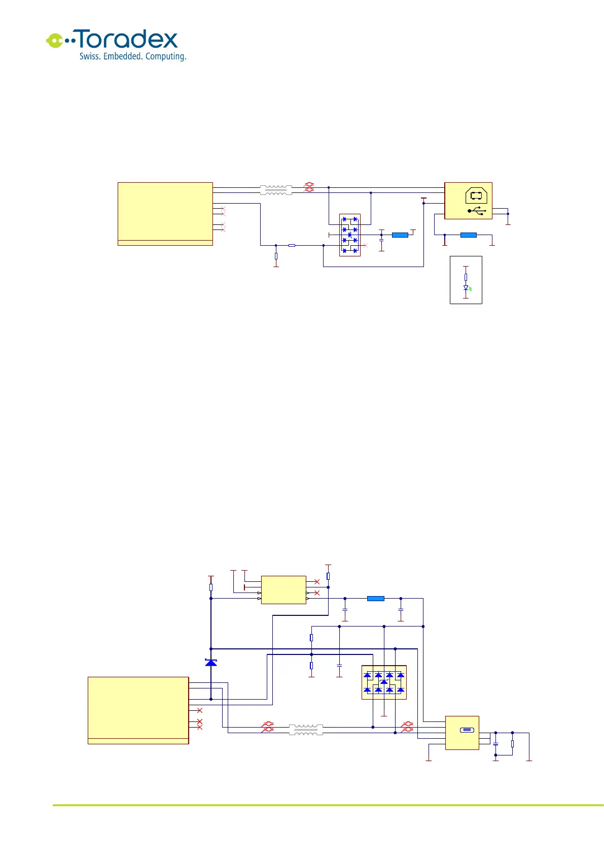
2.3.2.1 USB 2.0 Client Schematic Example
The differential USB data signals require a common mode choke to be placed. Make sure that the
selected choke is certified for USB 2.0 High Speed. The same is also required for the TVS diodes.
The VBUS_DETECT signal is only 3.3V tolerant on the Colibri module. The simplest solution is to
use a voltage divider.
Figure 3: USB 2.0 Client Reference Schematic
2.3.2.2 USB 2.0 OTG Schematic Example
The Colibri standard does not support the full USB OTG function. However, it is possible to
implement a circuit on the carrier board that allows changing the role from host to client
depending on the level of the ID pin of a Micro-AB jack. The reference schematic differs from other
USB OTG solutions since the module itself does not directly use the ID pin to detect whether the
port is supposed to be set in client or host mode. The pin is indirectly used.
If no cable is plugged into the Micro-AB jack, the port is configured to host mode, and the 5V
power output (VCC_USB2 in the schematic below) is disabled. If a Micro-B is plugged in (ID pin is
floating on such plugs), the VCC_USB2 comes from the cable since the system gets plugged into a
host. With the help of the voltage divider, the USB_C_DET signal gets around 3.3V. This signalizes
the module that it has been connected to a host and needs to switch to client mode.
If a Micro-A connector is inserted, the ID pin gets shorted to the ground. This ID pin enables the
output of the TPS2042 power switch. This voltage on the VCC_USB2 rail is used to power any client
device connected to the port. Additionally, the ID pin keeps the USB_C_DET signal low over a
diode, even though the VCC_USB2 rail goes to 5V. This makes sure the module remains in host
mode to be able to communicate with the client device that is plugged in.
Figure 4: USB 2.0 OTG Reference Schematic