Colibri Carrier Board Design Guide
Toradex AG l Altsagenstrasse 5 l 6048 Horw l Switzerland l +41 41 500 48 00 l www.toradex.com l info@toradex.com
3.4 Power States
The Colibri module and carrier board have different power states. The table below describes the
behavior during different states, and which power rails and peripherals are active. These are just
the standard power states. If additional power saving is necessary, it is possible to introduce other
states where some of the carrier board peripherals are switched off. In this case, a free GPIO can
be used to switch off unused peripheral power rails.
No power is applied to the
system, except the RTC battery
might be available
No main VCC and AVDD_AUDIO
applied. Maybe VCC_BACKUP
available
No power supply input, RTC
battery may be inserted
The system is suspended and
waits for wake-up sources to
trigger
CPU is suspended, wake-up
capable peripherals are running
while others might be switched
off
Power rails are available on the
carrier board. Peripherals might
be stopped by software
All power rails are available, CPU
and peripherals are running
All power rails are available.
Peripherals are running
The system is put in a reset state
by holding nRESET low
All power rails are available, CPU
and peripherals are in a reset
state
All power rails are available.
Peripherals are in a reset state
Table 28: Available Colibri Power States
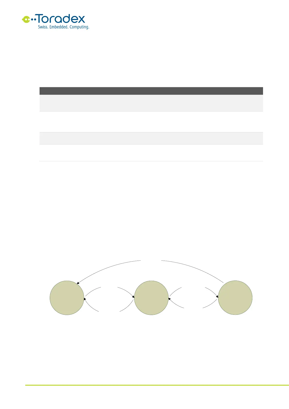
The figure shown below shows a sequence diagram of the different power states. The module
automatically goes into the running mode when the main power rail is applied to the module. In
the running mode, the system can be set to be suspended by the software. There might be
different wake-up sources available. Read the datasheet of the corresponding module for more
information about the available wake-up events. All Colibri modules have it in common that the
CTRL_WAKE_0 wakes up the module if the signal level goes low. If compatibility between the
modules is needed, use this pin as the general wake signal.
Unlike the Apalis module family, the Colibri modules do not provide a shutdown state in which the
module can switch off the carrier board peripheral supplies. The Colibri module does not have a
dedicated signal for turning off the peripheral supplies. Nevertheless, some modules can be shut
down (depending on the used operating system). In the standard carrier board architecture, all
power rails remain turned on.
Figure 28: Power State Diagram
3.5 Power-Up Sequence
The Colibri module starts booting as soon as the main voltage rail is applied to the module. The
main input voltage must rise monotonically. The RTC rail (VCC_BACKUP) needs to be applied
before or together with the main voltage. It is not allowed to apply the analog voltage supply
before applying the main voltage.
UPG
SUS
RUN
Apply VCC
to Module
Wake event
Suspend request
Remove VCC
from Module
Remove VCC
from Module