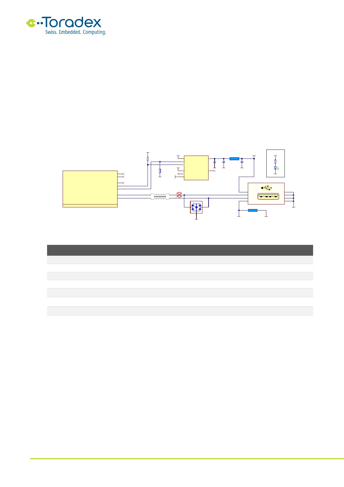
2.3.2.3 USB 2.0 Host Connector Schematic Example
The carrier board needs to provide 5V USB bus power on the USB host jacks. According to the USB
2.0 specifications, the maximum current drawn per port is limited by 500mA. The bus power needs
to be in the range of 4.75V to 5.25V measured at the USB host jack for any load current from 0mA
to 500mA. To ensure that an out-of-spec device or a defective device is not damaging the 5V
power rail on the carrier board, adding a current limiting IC is recommended. This device detects
an overcurrent situation and switches off the corresponding USB bus power. The overcurrent signal
(USB_H_OC) is used to notify the host controller about the occurrence of an overcurrent shutdown
event.
The inrush current needs to be taken into account while designing the USB bus power. USB devices
are allowed to have a maximum input capacitor at the bus power of 10µF. The maximum inrush
charge is limited to 50µC. This means that the power rail at the USB host jack needs to be tolerant
of this inrush current. A good approach is to place a large capacitor (e.g., 100µF) at the rail.
Figure 5: USB 2.0 Host Reference Schematic
2.3.3 Unused USB Signal Termination
Table 6: Unused USB Signals Termination
2.4 Parallel RGB LCD Interface
The Colibri modules feature one parallel RGB LCD interface as the primary display interface. As
standard, the Colibri modules feature an interface with 18-bit color depth. Some modules support
a color depth of 16-bit or 24-bit. Unfortunately, the color mapping of these modes can be different
between the modules. Therefore, Toradex recommends using the interface in the 18-bit color
mode for the best compatibility between all Colibri modules. Dithering can help to reduce the
visible color banding of gradients in lower color depth systems. Consider using 18-bit color
mapping with enabled dithering instead of 24-bit mapping. Carefully check which modules support
color dithering.