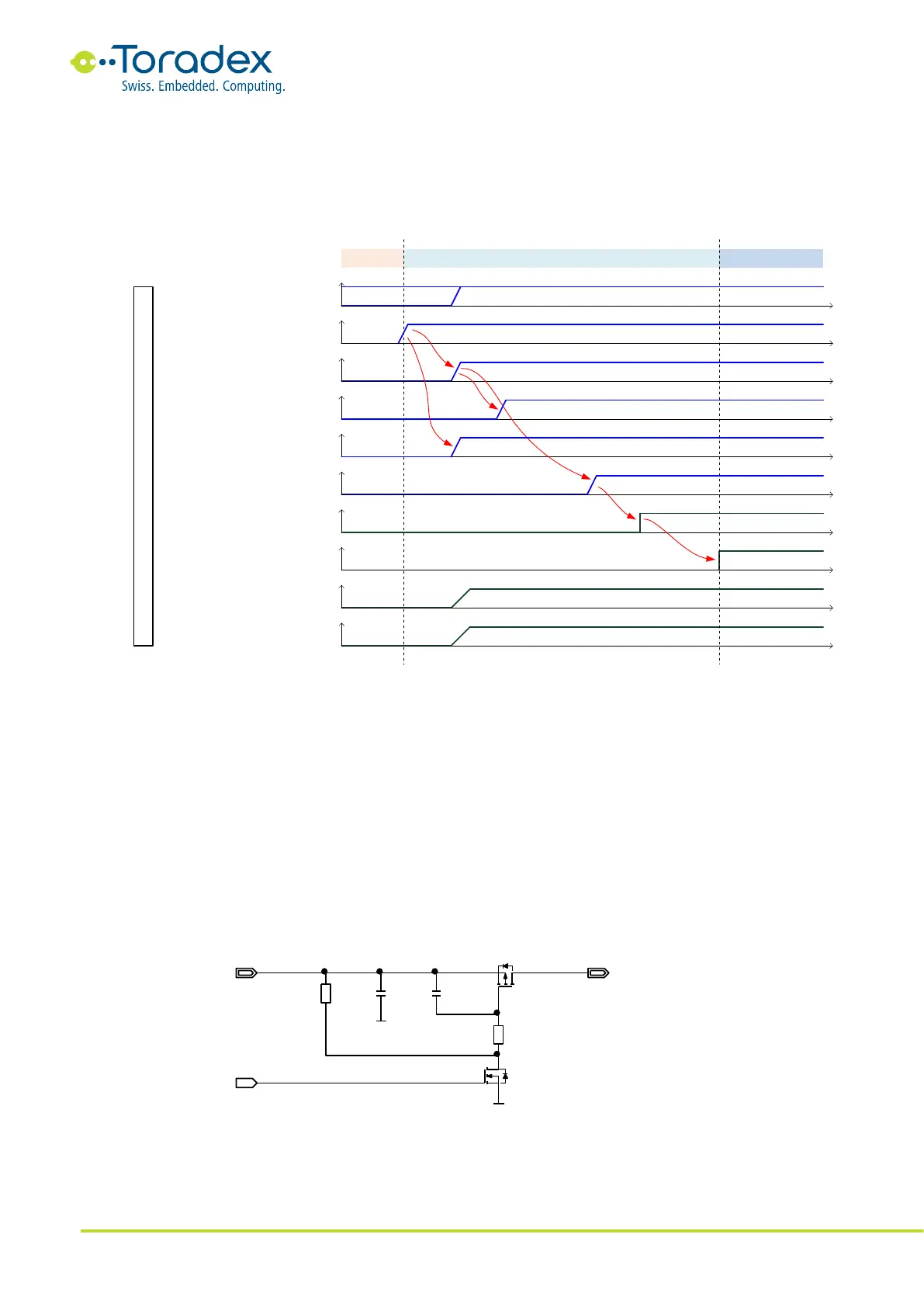
The peripheral power rails on the carrier board need to be ramped-up in a correct sequence. The
sequence starts typically with the highest voltage (e.g., 5V) followed by the lower voltages (e.g.,
3.3V, then 1.5V, and so on). Peripherals usually require that a lower voltage rail is never present if
a higher rail is missing. Check the datasheet of all peripheral components on the carrier board for
proper sequencing.
Figure 29: Power-Up Sequence
3.6 Reference Schematics
Place enough power supply bypass capacitors to the voltage inputs of the peripheral devices (see
Toradex Layout Design Guide). Place a bypass capacitor to each power input pin of the Colibri
module. Be aware of the total capacity on a voltage rail when switching the voltage. If the rails are
switched on too fast, the current peaks for charging all the bypass capacitors can be very high. This
can produce unacceptable disturbances or can trigger an overcurrent protection circuit. Maybe the
switching speed needs to be limited. The following figure shows a simple voltage rail switch circuit.
C1 and R1 limit the switching speed. The values need to be optimized according to the
requirements. It is recommended to place a bypass capacitor (C2) close to the switching transistor.
Figure 30: Simple Voltage Switch Circuit
To satisfy the in-rush current during the start-up of a Colibri module, we recommend using bulk
capacitors of about 450µF in total on the main 3.3V power supply.