Colibri Carrier Board Design Guide
Toradex AG l Altsagenstrasse 5 l 6048 Horw l Switzerland l +41 41 500 48 00 l www.toradex.com l info@toradex.com
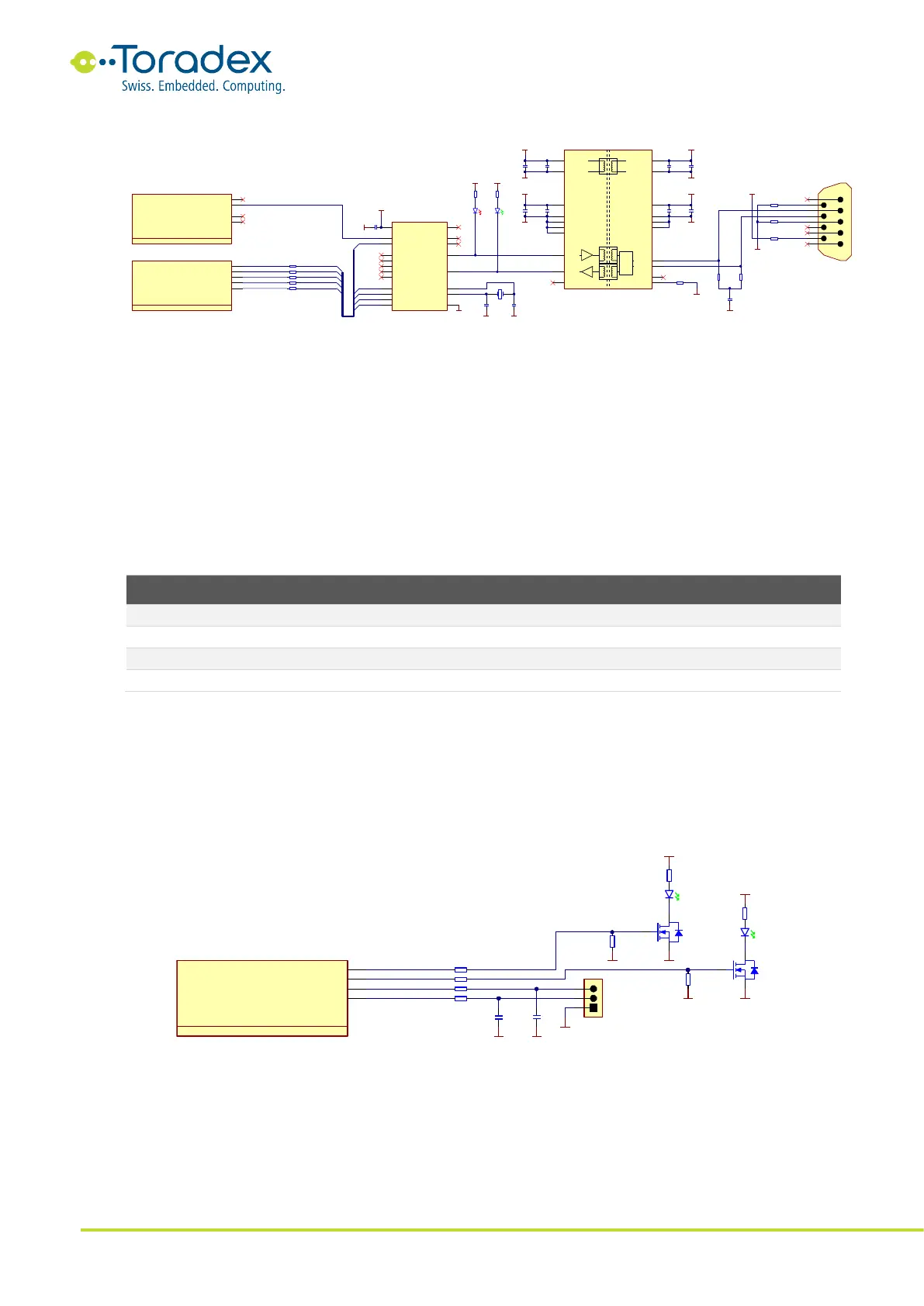
Figure 21: CAN Reference Schematic
2.13 PWM
The Colibri module form factor defines four general-purpose pulse width modulator (PWM)
outputs. Please note that two of the four PWM signals are located on pins that are also used for the
standard parallel camera interface. These PWM outputs can only be used if the according camera
pins are not in use. The maximum output frequency and the available duty cycle steps can also
vary between the different Colibri modules.
2.13.1 PWM Signals
General-purpose PWM output, pin also used for camera interface
General-purpose PWM output
General-purpose PWM output
General-purpose PWM output, pin also used for camera interface
Table 19: PWM Signals
2.13.2 Reference Schematics
The PWM output signals can be used for example, to drive motors, LEDs, robotic servos, or fans. It
is possible to get an analog signal with a simple low-pass filter. A widespread usage is driving of
the backlight of liquid crystal displays.
Figure 22: PWM Example Schematic
2.13.3 Unused PWM Signal Termination
Unused PWM signals can be left unconnected.
1473005 -1
PIN_86 / SSPFRM
86
PIN_88 / SSPSCLK
88
PIN_90 / SSPRXD
90
PIN_92 / SSPTXD
92
Colibri - SSP/CAN
6 of 16
PIN_73 / CAN_INT#
73
X1F
SODIMM_86
SODIMM_88
SODIMM_90
SODIMM_92
SODIMM_73
MCP2515 T-I/ST
TX CAN
1
RXCAN
2
CLKOUT/SOF
3
nTX0RTS
4
nTX1RTS
5
NC
6
nTX2RTS
7
OSC2
8
OSC1
9
VSS
10
VDD
20
nRESET
19
nCS
18
SO
17
SI
16
NC
15
SCK
14
nINT
13
nRX0BF
12
nRX1BF
11
IC18
SSP_SCLK
SSP_FRM
SSP_TXD
SSP_RXD
CAN_INT#
100nF
16V
C159
GND
3.3V
GND
16.0 MHz
1 2
OSC3
22pF
50V
C163
22pF
50V
C162
GND GND
RESET_OUT #
22 RRA11A
22 RRA11B
22 RRA9C
22 RRA9D
22 RRA30C
CAN_TX
CAN_RX
100nF
16V
C105
100nF
16V
C106
CAN_L
CAN_H
CAN_ GND_I SOGND
CAN_5V_ISO
0R
R10 6
3.3V
CAN_GND_I SO
5V
ADM3053BRWZ
VCC
8
VIO
6
VISOOUT
12
VISOIN
19
VREF
14
RXD
4
TX D
5
CANL
15
CANH
17
RS
18
GND1_2
3
GND1_3
9
GND1_4
7
GND1_5
10
GND1_1
1
GND2_2
11
GND2_3
16
GND2_4
13
GND2_1
20
NC
2
CAN
IC10
10uF
10V
C104
10uF
10V
C107
100nF
16V
C109
GND
10nF
25V
C108
100nF
16 V
C111
10nF
25V
C110
CAN_5V_ISO
CAN_ GND_I SO
56R
R107
56R
R108
47nF
16 V
C112
CAN_ GND_I SO
CAN_PGND
R99
100 R
CAN_PW
U1
U2
U3
U4
U5
U6
U7
U8
U9
178- 009- 613R571
X32A
CAN Connector
CAN_5V_ISO
CAN_ GND_I SO
0R
R100
0R
R101
NA
NA
GREEN
LED16
RED
LED17
R90
120R
R91
120R
3.3V 3.3V
SSP_SCLK
SSP_FRM
SSP_TXD
SSP_RXD
CAN_INT#
1473005 -1
VDD_ FAULT#
BATT_ FAULT#
24
RESET_EXT#
26
RESET_OUT #
Colibri - Reset
4 of 16
X1D
87
22
1473005 -1
PIN_59 / PW M_A
59
PIN_67
PIN_28 / PW M_B
28
PIN_30 / PW M_C
30
Colibri - PWM
5 of 16
X1E
SODIMM_59
SODIMM_28
SODIMM_30
SODIMM_67
R98
10K
R99
10K
330nF
16 V
C155
GND GND
22RRA33A
22RRA29D
3
5
4
SI-1024-X
T5B
2
1 6
SI-1024-X
T5A
GREEN
LED3
R124
120 R
3.3V
GND
R128
100 K
3.3 V
GNDGND
GND
GREEN
LED4
120 R
R131
100 K
1
2
3
X2
GND
PWM_A
PWM_B
PWM_C
PWM_D
330nF
16 V
C154
67