2.10.2.3 RS485 Reference Schematics
The RS485 interface is a half-duplex serial interface with differential pair signals. Instead of two
differential pair wires (RS422), only one pair is used for transmitting and receiving the data. The
bus allows multi-point connections. An additional control signal is required since the transceiver
needs to be set either in the transmitting or receiving mode. It is recommended to use the RTS
signal of the corresponding UART interface. The RTS signal is only available on the UART_A and
UART_B as a Colibri standard interface. The schematic below inverts the RTS signal for the data
enable input of the transceiver. Some modules allow inverting the signal in software. However, it is
recommended to use the inverter circuit shown below to maintain compatibility with different
modules and drivers provided by Toradex. For some applications, the UART controller should not
see the TX message on its RX pins (the echo of the sent message). In this case, the receive enable
pin (RE#) can be driven with the RTS signal. This turns off the RX output buffer while sending a
message.
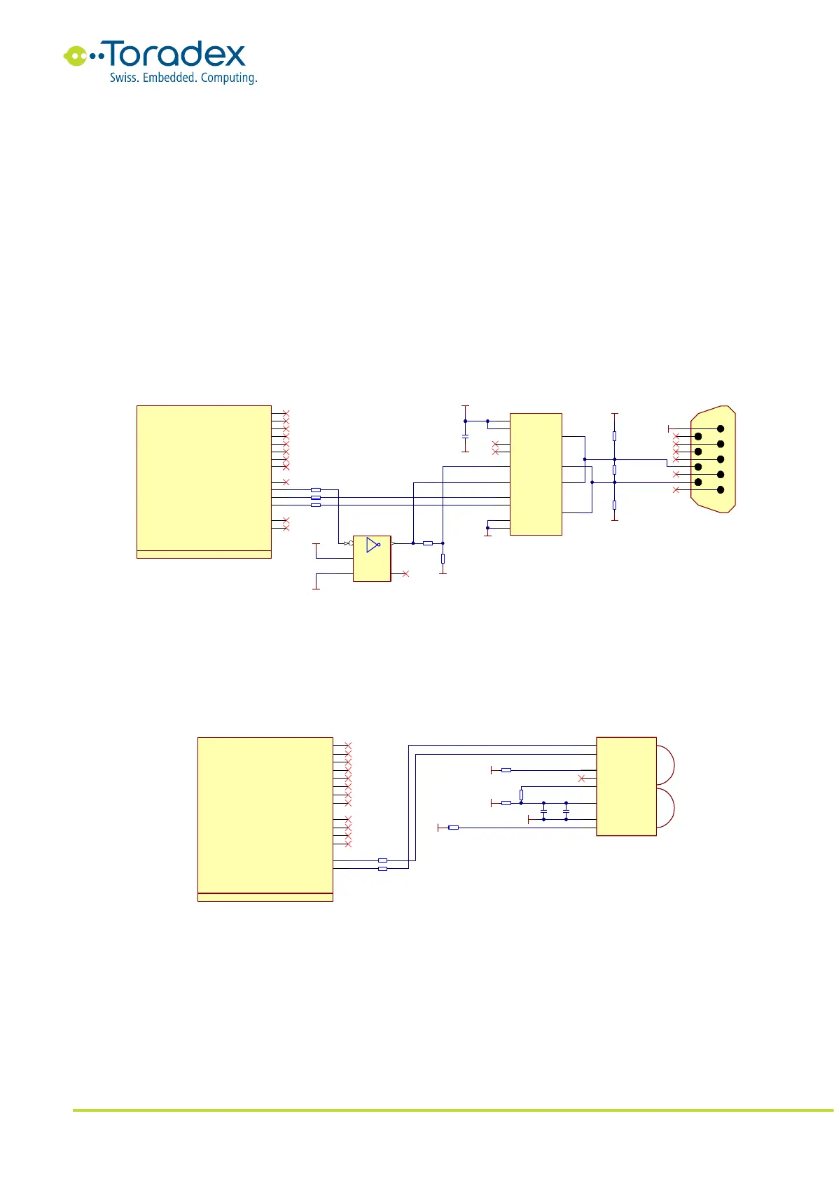
Like the RS422, the RS485 specification also does not describe a standard connector. The reference
schematic below uses a DE-9 connector which may have a different pinout as some peripheral
devices.
Figure 19: RS485 Reference Schematic
2.10.2.4 IrDA Reference Schematics
IrDA is an optical wireless communication interface. There are different physical layer modulation
schemes available. Make sure which modes are supported by the specific Colibri module and the
peripheral devices. For compatibility reasons, it is recommended to use UART_C for the IrDA
implementation. Some modules only feature the IrDA function on this UART instance.
Figure 20: IrDA Reference Schematic
2.10.3 Unused UART Signal Termination
Unused UART interface signals can be left unconnected. For debugging purposes, it is
recommended to have at least the UART1_RXD and UART1_TXD signals available.