2.8.2 Reference Schematics
Even if the selected module does not require pull-up resistors on the data and command lines, it is
recommended to place such resistors in the customer design and just not assemble them. This
makes sure that the module is compatible with other Colibri modules. There is no dedicated card
detect signal available. Any free GPIO capable signal could be used, but we recommend using the
signal on Pin 43 (CTRL_WAKE_0) whenever possible. There is also no dedicated write protection
signal available on the standard Colibri pinout. Any free GPIO capable signal can be used if the
write protection function is required.
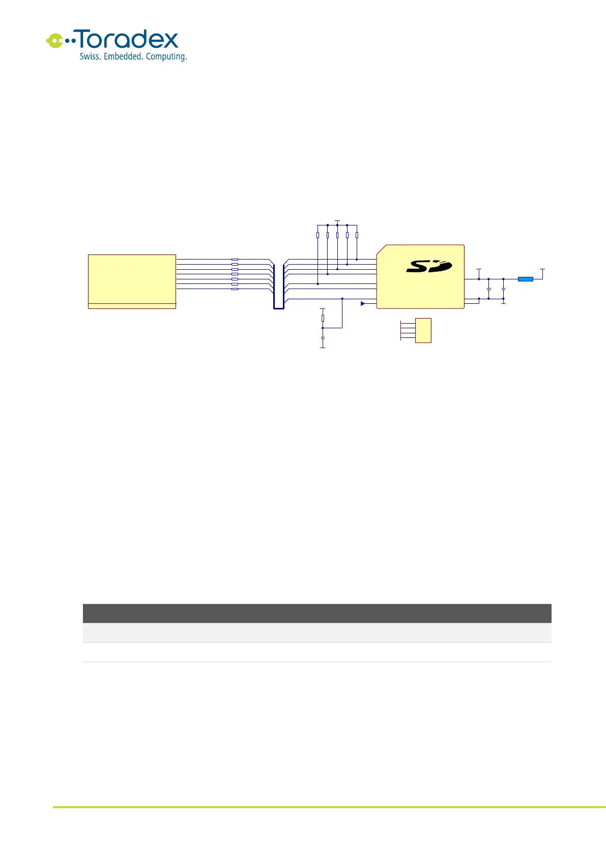
2.8.2.1 SD Card Slot Reference Schematics
Figure 15: SD Card Slot Reference Schematic
2.8.3 Unused SD/MMC/SDIO Interface Signal Termination
All unused SD interface signals can be left unconnected.
2.9 I
2
C
The Colibri module form factor features one general-purpose I
2
C interface. Additionally, some
Colibri modules feature a dedicated DDC interface on the HDMI FFC connector.
The I
2
C, as well as the DDC interfaces, do not feature any pull-up resistors on the module. It is
required to add pull-up resistors to the data and clock lines on the carrier board. The pull-up
resistor values usually are between 1kΩ and 10kΩ. A small pull-up resistor increases power
consumption, while a large resistor could lead to signal quality problems. The optimum size of the
resistor depends on the capacitive load on the I
2
C lines and the required bus speed. 4.7kΩ is a
suitable value for many applications.
2.9.1 I
2
C Signals
Table 14: I
2
C Signals
2.9.2 Real-Time Clock (RTC) recommendation
The RTC on the module is not designed for ultra-low power consumption. Therefore, a standard
lithium coin cell battery can drain faster than allowed for certain designs. If a rechargeable RTC
battery is not the solution, it is recommended to use an external ultra-low power RTC IC on the
carrier board instead. In this case, add the external RTC to the I
2
C interface of the module.