EasyManua.ls Logo

Toradex Colibri - C Signal Termination; Uart; UART Signals

Default Icon
66 pages
Print Icon
To Next Page IconTo Next Page
To Previous Page IconTo Previous Page
Loading...
Colibri Carrier Board Design Guide
Toradex AG l Altsagenstrasse 5 l 6048 Horw l Switzerland l +41 41 500 48 00 l www.toradex.com l info@toradex.com
Page | 26
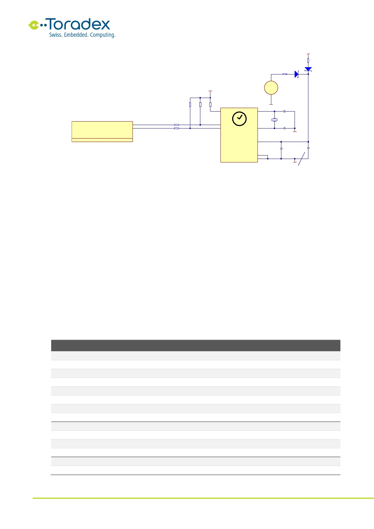
Figure 16: External RTC Reference Schematic
2.9.3 Unused I
2
C Signal Termination
All unused I
2
C can be left unconnected if the corresponding I
2
C port is switched off in software.
Otherwise, it is recommended to keep the pull-up resistors available. Unused I
2
C signals can be
configured to be GPIO.
2.10 UART
The Colibri module form factor features three UART interfaces. Even though the UART_A is
specified as full-featured UART, some modules might not provide all the control signals. Please
read the corresponding datasheet of the module carefully. UART_A is the standard console output
interface for the Linux and Windows Embedded Compact operating system. It is desirable to keep
at least the RX and TX signals of this port accessible for system debugging.
UART_B features RTS and CTS signals for hardware flow control, while UART_C does not feature
any flow control signals. Some modules might provide the additional flow control signals on non-
standard pins.
2.10.1 UART Signals
Colibri
Pin
Colibri
Signal Name
I/O
Type
Power
Rail
Description
33
UART_A_RX
I
CMOS
3.3V
Received Data
35
UART_A_TX
O
CMOS
3.3V
Transmitted Data
27
UART_A_RTS
O
CMOS
3.3V
Request to Send
25
UART_A_CTS
I
CMOS
3.3V
Clear to Send
23
UART_A_DTR
O
CMOS
3.3V
Data Terminal Ready
29
UART_A_DSR
I
CMOS
3.3V
Data Set Ready
37
UART_A_RI
I
CMOS
3.3V
Ring Indicator
31
UART_A_DCD
I
CMOS
3.3V
Data Carrier Detect
36
UART_B_RX
I
CMOS
3.3V
Received Data
38
UART_B_TX
O
CMOS
3.3V
Transmitted Data
34
UART_B_RTS
O
CMOS
3.3V
Request to Send
32
UART_B_CTS
I
CMOS
3.3V
Clear to Send
19
UART_C_RX
I
CMOS
3.3V
Received Data
21
UART_C_TX
O
CMOS
3.3V
Transmitted Data
Table 15: UART Signals
GND
100nF
16V
C93
M41T0M6
OSCI
1
OSCO
2
VCC
VSS
4
NF
3
OUT
7
SCL
6
SDA
5
IC7
R47
100K
3.3V
R45
4.7K
R4 6
4.7K
32.768 KHz
1 2
OSC1
BAT54
D8
3.3V
GND
22uF
25 V
C9 2
1473005 -1
PIN_194 / I2C_SDA
194
PIN_196 / I2C_SCL
196
Colibri - I2C
7 of 16
X1G
GND
10R
R49
BAT54
D9
SODIMM_194_S
SODIMM_196_S
HU2032- LF
+
1
-
2
BAT1
470R
R48
22RRA32C
22RRA32D
Backup during Battery change: about 0.6 sec/uF
27pF
50 V
C91
27pF
50 V
C90
8

Table of Contents

Related product manuals