Colibri Carrier Board Design Guide
Toradex AG l Altsagenstrasse 5 l 6048 Horw l Switzerland l +41 41 500 48 00 l www.toradex.com l info@toradex.com
3.2.3 Power Management Signals
nRESET_EXT
(CTRL_RESET_MICO#)
nRESET_OUT
(CTRL_RESET_MOCI#)
Active-low primary module wake input signal, needs a pull-up
resistor on the baseboard if wake function is used
Only available on PXA270, can be left unconnected
Only available on PXA3xx, can be left unconnected
Only available on PXA270 and PXA3xx, can be left unconnected
Table 27: Power Management Signals
To make the direction of the power management signals clear, the ending MICO or MOCI is
added. MICO is the abbreviation for "Module Input, Carrier board Output", while MOCI stands for
"Module Output, Carrier board Input".
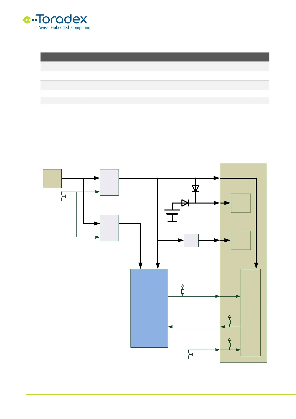
3.3 Power Block Diagram
Figure 26: Power Block Diagram
7-24V
Enable
Enable
Module
3.3V
RTC
nRESET_EXT
nRESET_OUT
CTRL_WAKE_0
5V
Analog
Circuit
AVDD_AUDIO
VCC_BACKUP
VCC
3.3V
Filter
5V
Buck
3.3V
Buck
Peripheral
Devices on
Carrier Board
Power Management
RTC
Battery
7-24 V
input
Jack
For better quality use
dedicated LDO from 5V rail