Colibri Carrier Board Design Guide
Toradex AG l Altsagenstrasse 5 l 6048 Horw l Switzerland l +41 41 500 48 00 l www.toradex.com l info@toradex.com
The nRESET_EXT and nRESET_OUT do not need any pull-up resistors on the carrier board since
these resistors are already placed on the module. The CTRL_WAKE_0 requires a pull-up resistor on
the carrier board if the wake function is implemented.
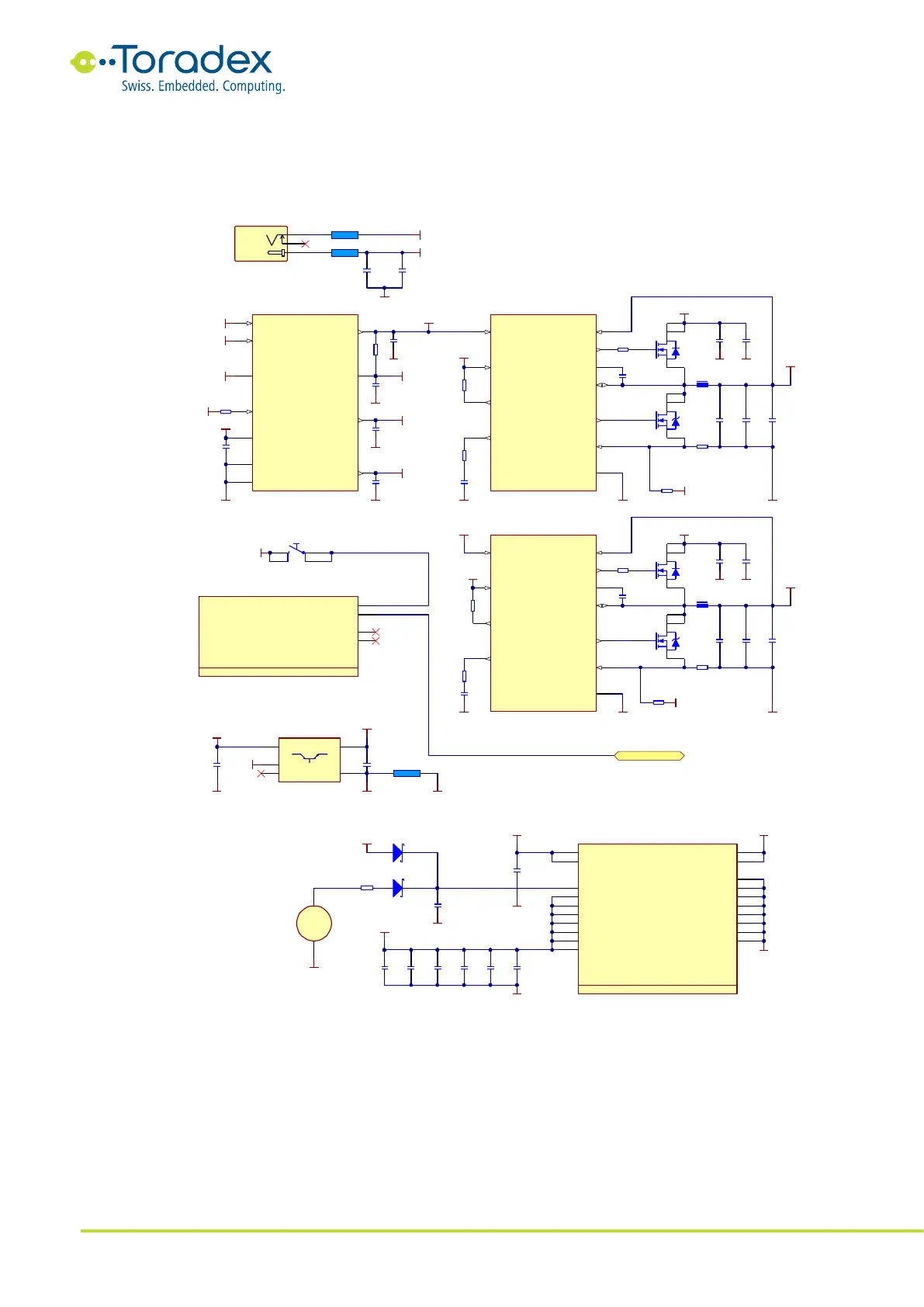
Figure 31: Simple Power Supply Reference Schematic
GND
VREF2
GND
TPS51120
EN5
9
EN3
10
GND
32
TONSEL
31
VIN
22
GND
5
HS
33
VREF2
4
VREG3
V5FILT
VREG5
100m A nom .
200m A max.!
100m A nom .
200m A max.!
IC5A
10uF
6.3V
C6
GND
VREG3
GND
1uF
16 V
C6 7
GND
V5FI LT
R34
4.7R
0RR36
GND
V5FILT
R35
100 K
R38
6.2K
2.7nF
50V
C75
GND GND
GND
Place sense resistor close to TPS
15mRR37
pin 24 and input capacitors
24m RR44
100nF
16 V
C6 6
100nF
16 V
C7 8
R3 3
4.7 R
R4 1
4.7 R
FDS6982AS
4
3
5
6
T1B
FDS6982AS
2
1
7
8
T1A
TP S5112 0
EN
29
VFB
3
PGOOD
30
COMP
2
LL
26
VBST
28
DR VH
27
VO
1
PGND
24
CS
23
DR VL
25
IC5B
TP S5112 0
EN
12
VFB
6
PGOOD
11
COMP
7
LL
15
VBST
13
DR VH
14
VO
8
PGND
17
CS
18
DR VL
16
IC5C
FDS6982AS
2
1
7
8
T2A
FDS6982AS
4
3
5
6
T2B
GND
GND
GND
GND
V5FILT
R42
100 K
GND
R43
10K
5V
3.3V
VREG5
10uF
10V
C65
GND
GND
GND
1nF
50V
C87
10uF
50V
C8
10uF
50V
C9
10uF
50V
C2
10uF
50V
C1
8.2u H
6.25 A
L2 0
4.7u H
6.2A
L2 1
V5FILT
R157
3.3K
R156
3.6K
V5FILT
150uF
10V
+
C3
150uF
10 V
+
C4
C5
1nF
50V
C7 4
150uF
10V
+
C10
150uF
10 V
+
C11
NA
NA
NA
NA
10uF
50V
C7
VREG5
Reset Button
GND
1
2
3
4
SW2
TD -03XB
RESET_MICO#
RESET_MOCI#
RESET_MOCI#
RESET_MOCI#
RAPC722X
1
2
PW R_IN
GND_IN
3
X2
36R @ 100MHz
10 A
L2
10uF
50 V
C1 5
10uF
50V
C1 4
GND
12V_FILT_UNREG
36R @100MHz
10 A
L1
GND
12V_FILT_UNREG
12V_FILT_UNREG
12 V_FILT_UNREG
12 V_FILT_UNREG
Power IN
1473005 -1
VDD_ FAULT#
22
BATT_FAULT#
24
RESET_EXT#
26
RESET_OUT#
87
Colibri - Reset
4 of 16
X1D
VREG5
3.3V
2.2uF
6.3V
C89
GND
5V
2.2uF
6.3V
C8 8
2A
220R@ 100MHz
L2 4
GND
Place bead close to pin 9/11 on Colibri SODIMM Connector
Vin
1
GND
2
N/C
4
Vout
5
E
3
NC P511SN33T1G
IC6
Audio VCC Circuit
GND
AUDIO_AVCC
AUDI O_AGND
1473005 -1
GND
39
GND
41
GND
83
GND
109
GND
147
GND
181
GND
197
GND
199
VCC_ BATT
40
3V3
42
3V3
108
3V3
182
3V3
198
3V3
200
3V3
84
3V3
148
PIN_9/ VSS_AUDIO
9
PIN_11/VSS_AUDIO
11
Colibri - Power Supply
1 of 16
VDD_ ANALOG
10
VDD_ ANALOG
12
X1A
100nF
16V
C7 1
GND
BAT54
D14
3.3V
VCC_INTRTC
Place close to SODIMM pins
GND
4.7uF
10V
+
C80
4.7uF
10 V
+
C81
4.7uF
10V
+
C82
22uF
10V
+
C79
3.3 V
Module Power Supply
GND
10 R
R4 9
BAT54
D9
HU2032-LF
+
1
-
2
BAT1
100nF
16V
C93
GND
100nF
16V
C94
100nF
16V
C95
Reset for peripherals
150uF
10 V
+
C12
150uF
10 V
+
Place sense resistor close to TPS
pin 17 and input capacitors
AUDIO_AVCC
AUDIO_AGND
21
20
19