14 Installation On Site SWINGDOOR Smart Drive 1101 T-1132 e
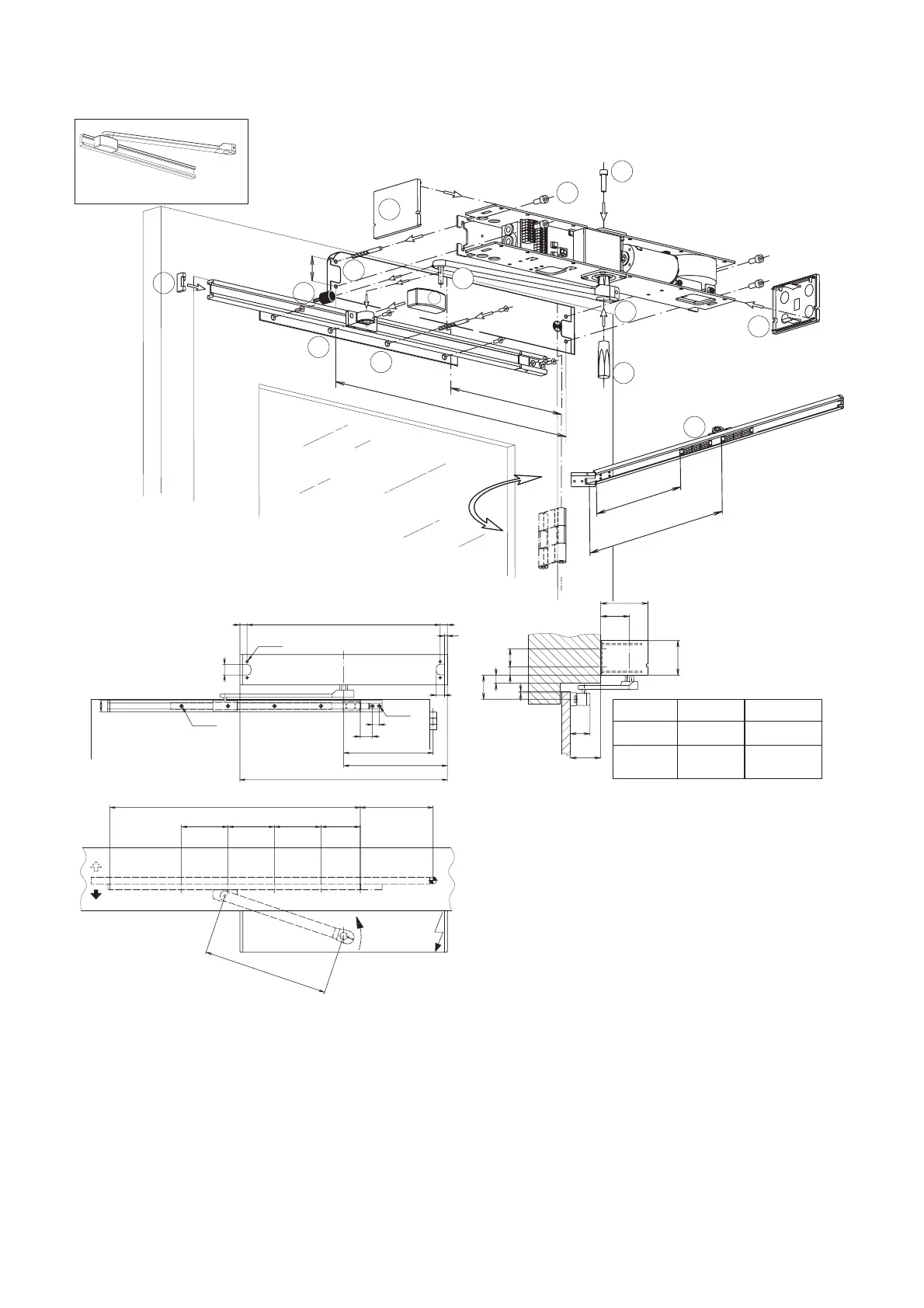
4.4 Panic Fitting ◆
T1132/11
C
D
G
K
A
B
540
250
45
F
H
I
T1132/23
E
400
100 ... 300
L
N
M
M
U
W
0 – 20 59 ± 3
X
0…+150
0 – 80 119 ± 3
0…+150
X
20
70.5
116
W
U
3±3
85
45
49
540
20
4x Ø5
4x Ø7
30
290
20
23
32
250
580
8
4x Ø5
34
19
160 + X/2
350
130
130 130 110
700
T1132/44
A) Glue on template
B) Drill holes
C) Attach cone (length according Y)
D) Tighten hexagon-socket screw in a way that the
cone can be turned by hand
E) Fasten operator
F) Fasten hinge of panic fitting and holding plate
according to dimensional specifications on door
leaf
G) Adjust the desired holding force of the magnet by
sliding it in the rail.
H) insert bearing trestle into sliding rail
I) Mount side covers of sliding rail
Connect to mains,
Trigger factory reset, (see paragraph 7.3 programmimg table)
Choose operating mode OPEN (only with operating mode switch ◆ or by connecting terminals no 2 and 3)
axis will turn 20°
K) Slide connecting part over cone and push up to the operator
insert other end completely into bearing threstle, tighten cone (hexagon-socket screw) and connecting part
L) Fasten cover
M) Snap in side plates
N) Fasten rubber stop on the lintel, so that the connecting part will rest on it, when triggering the panic fitting.