16 Installation On Site SWINGDOOR Smart Drive 1101 T-1132 e
6 Electrical Connections
Observe wiring diagram T-1135 e for lintel mounting and T-1154 e for door-leaf mounting!
A system switch must be mounted on site.
Before beginning the work described here check that the mains supply is switched off.
If possible, route the mains connection along the side of the power supply to the operator.
The connecting cables must be of the type “PVC cable H05VV-F” or “rubber hose cable
H05RR-F”.
Round the edges and remove burrs from all conduits used for the mains connection.
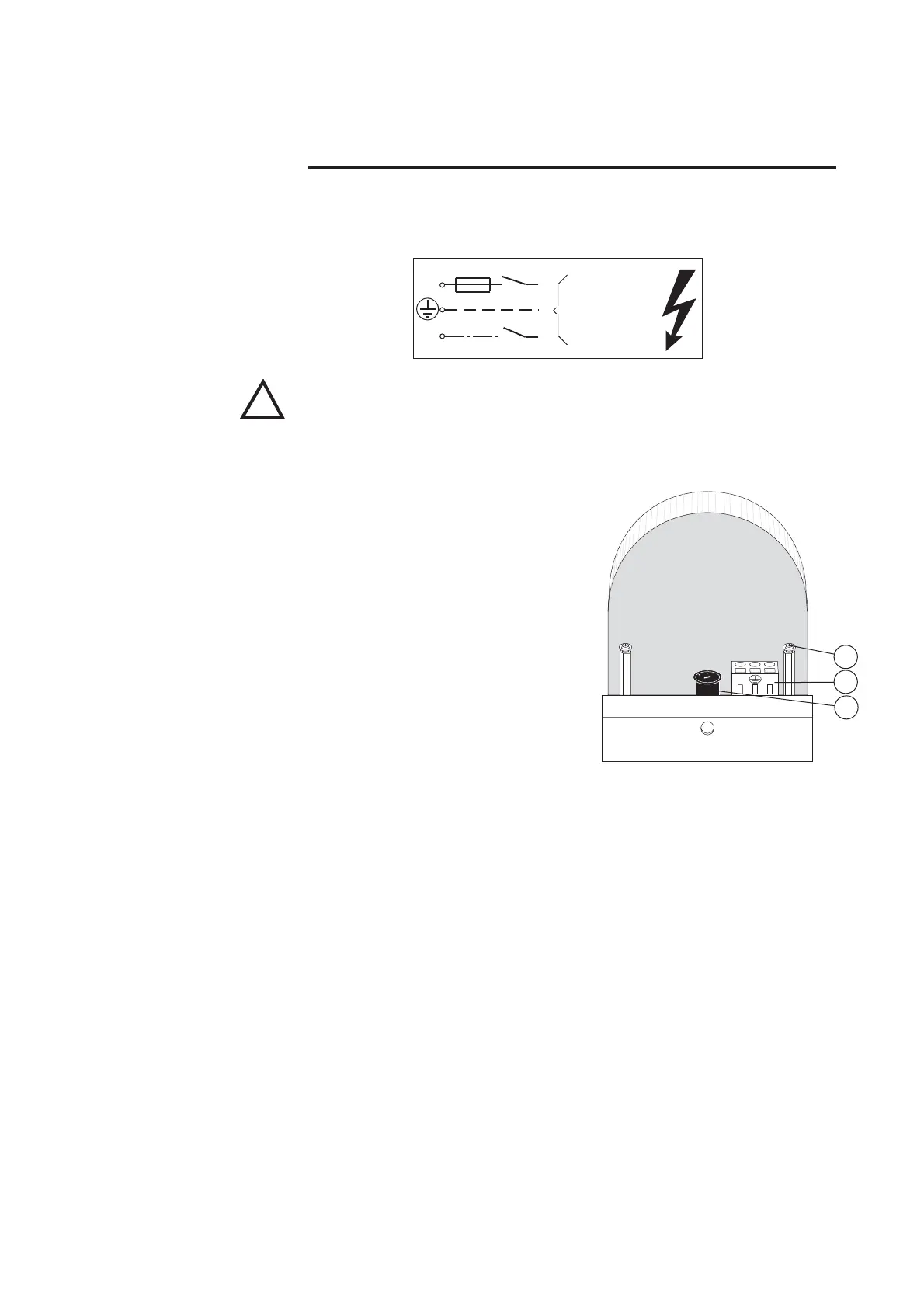
• Remove mains supply cover (1).
• Connect the mains cable to terminal (11) in
accordance with figure.
• Route the mains cable either through the
prepared holes of the side cover or through
the slots in the mounting plate.
• Use only cable bushings made from syn-
thetic materials. Metallic bushings are to be
earthed.
• Check correct adjustment of the voltage
selector (12) and reinstall the mains supply
cover (1).
• Secure mains cable with a cable strap at the
plastic nub (17) and at the supporting metal
sheet.
• Mount the emergency-off switch in accordance with the contract order and route the
mains connection via emergency-off switch.
• Mount in accordance with contract order
• Connect in accordance with connection diagram and the manufacturer’s specification
• Adjust the detection field/sensitivity and action radius according to the requirements
and the surroundings of the system.
10AT
L1
3mm
N
230/115V~
50/60 Hz
T1132/1
!
Mains Connection
Emergency-off Switch ◆
T1132/34
L1
N
12
11
1
Activator and Safety
Facilities ◆