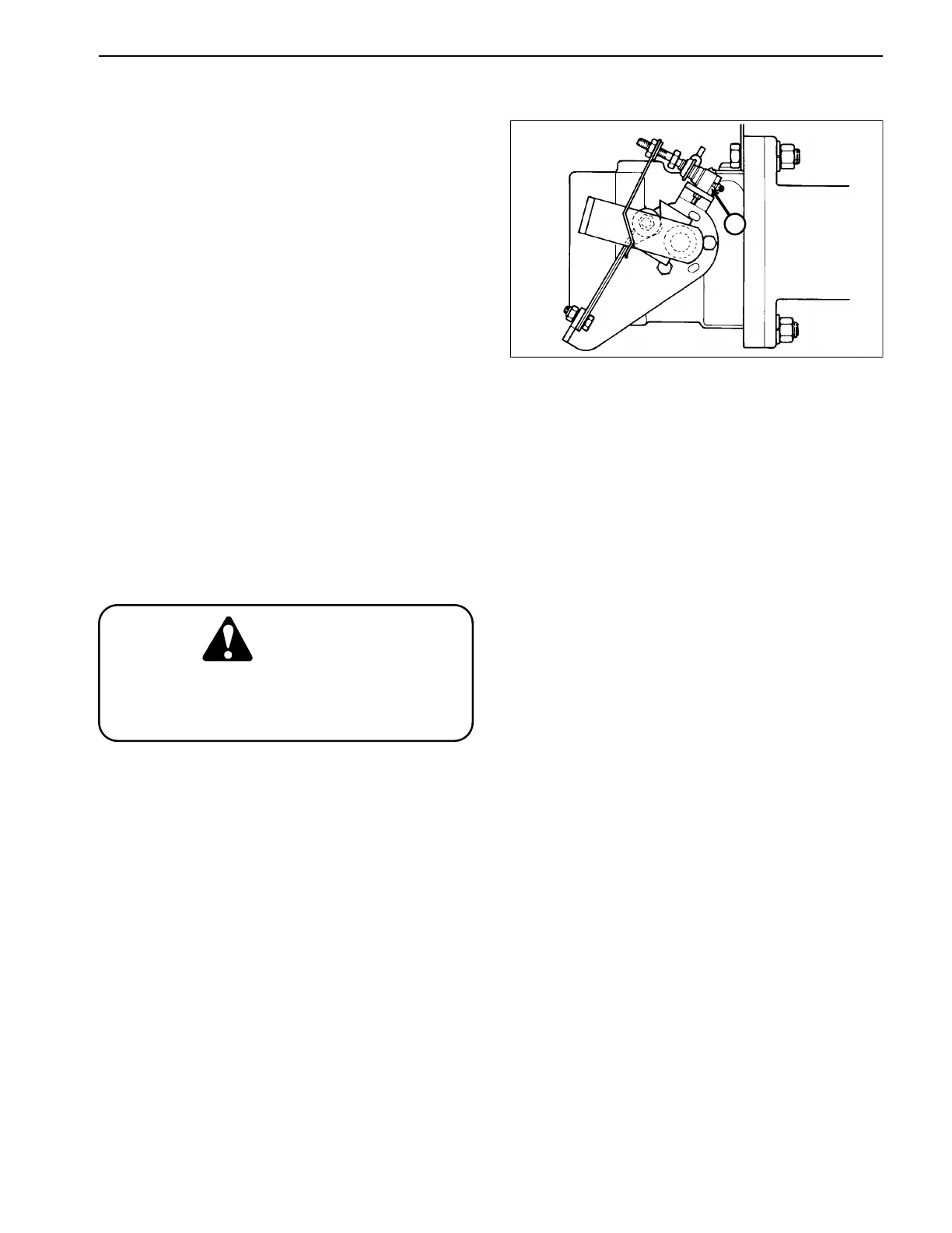
Traction (Neutral) Switch Replacement (Fig. 31)
1. Remove the two wires that are connected to the
traction switch.
2. Have a helper push the traction pedal down into either
the FORWARD or REVERSE position; this will take the
switch arm tension off of the switch. Loosen two (2)
screws and remove the switch.
3. Install new switch. DO NOT over-tighten screws as
the switch case could break.
NOTE: Apply “Loctite 271” or equivalent to threads of
switch screws before installing.
NOTE: Have a helper hold the traction pedal down while
Figure 31
installing the switch.
1
1. Traction (neutral) switch
4. Reconnect the two wires to the new switch. Make sure
that one wire is connected to the “COMMON” terminal,
and one wire is connected to the “NORMALLY OPEN”
(N.O.) terminal.
IMPORTANT: The traction switch has three (3) ter-
minals. If the two (2) wires are not connected to the
“COMMON” and “NORMALLY OPEN” (N.O.) termi-
nals, the engine will be unable to start and the safety
interlock circuit will not function properly.
If the wires are not correctly installed to the
switch, the engine could start with the trac-
tion pedal in forward or reverse.
CAUTION
5. Coat the switch terminals and wires with skin-over
grease.
6. Check traction control neutral adjustment. (See Trac-
tion Control Neutral Adjustment in the Adjustments sec-
tion of Chapter 4 - HYDRAULIC SYSTEM.
Reelmaster
®
216/216-D Page 6 - 33 Repairs
 Loading...