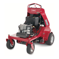
Figure56
1.Transmissionpullys4.Enginepulley
2.Transmission5.Tensionerpulley
3.Socket(belt-tension
bracket)
3.Slipthetransmission-drivebeltoftheengine,tensioner,
andtransmissionpulleys(Figure56).
4.Routethenewtransmission-drivebeltaroundthe
engine,tensioner,andtransmissionpulleysasshown
inFigure56
5.Releasethebelt-tensionbracketandallowthespringto
tensionthebelt(Figure56).
Note:Makesurethebelt-tensionbracketandpulley
canmovefreely.
ControlsSystem
Maintenance
AdjustingtheTraction-Control
Linkage
1.Parkthemachineonalevelsurface.
2.Stoptheengine,settheparkingbrake,removethekey,
andwaitforallmovingpartstostopbeforeleavingthe
operatingposition.
3.Pushthecontrolleverallthewayforwardtothefront
referencebar.
4.Ifthecontrollevercontactthereferencebarordo
notcontactthereferencebarperformthefollowing:
A.Releasethecontrolleverandallowittoreturnto
theneutralposition.
B.Removethespring-clevispinfromtheforktting
ofthetraction-controllinkage(Figure57).
Figure57
1.Spring-clevispin
3.Turnbuckle
2.Locknut
C.Adjusttheforkttingtosettheinitialgapas
follows:
•Ifthecontrollevercontactsthereference
bar,rotatetheforktting(Figure57)
counterclockwise(asviewedfromthetopof
themachine).
•Ifthecontrolleverdoesnotcontactsthe
referencebar,rotatetheforktting(Figure
57)counterclockwise.
D.Installthespringclevispin(Figure57)andmove
thecontrolleverforward.
E.RepeatthisstepsAthroughDuntilthereisagap
approximately1.6mm(1/16inch)betweenthe
controlleverandthefrontreferencebar.
43