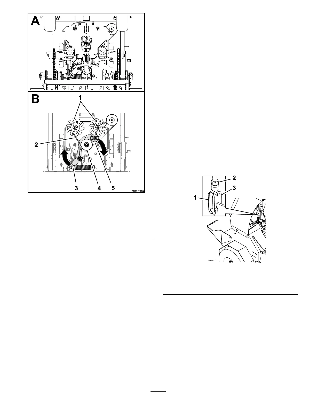
g025999
Figure58
1.Transmissionpulley4.Enginepulley
2.Transmission5.Tensionerpulley
3.Socket(belt-tension
bracket)
3.Slipthetransmission-drivebeltoftheengine,
tensioner,andtransmissionpulleys(Figure58).
4.Routethenewtransmission-drivebeltaround
theengine,tensioner,andtransmissionpulleys
asshowninFigure58
5.Releasethebelt-tensionbracketandallowthe
springtotensionthebelt(Figure58).
Note:Makesurethatthebelt-tensionbracket
andpulleycanmovefreely.
ControlsSystem
Maintenance
Adjustingthe
Traction-ControlLinkage
1.Parkthemachineonalevelsurface.
2.Shutofftheengine,engagetheparkingbrake,
removethekey,andwaitforallmovingpartsto
stopbeforeleavingtheoperatingposition.
3.Pushthecontrolleverallthewayforwardtoward
thefrontreferencebar.
4.Ifthecontrollevercontactsthereference
barorIfthegapbetweenthecontrolleverand
referencebarislargerthan1.6mm(1/16inch),
performthefollowing:
A.Releasethecontrolleverandallowitto
returntotheneutralposition.
B.Removethespring-clevispinfromthefork
ttingofthetraction-controllinkage(Figure
59).
g020223
Figure59
1.Spring-clevispin
3.Turnbuckle
2.Locknut
C.Adjusttheforkttingtosettheinitialgap
asfollows:
•Ifthecontrollevercontactsthe
referencebar,rotatetheforktting
(Figure59)counterclockwise(asviewed
fromthetopofthemachine).
•Ifthegapbetweenthecontrolleverand
referencebarislargerthan1.6mm
(1/16inch),rotatetheforktting(Figure
59)counterclockwise.
D.Installthespringclevispin(Figure59)and
movethecontrolleverforward.
50