andtensionerplate,andthe2nutssecuringthe
adjustmentboltatthetensionerplateasshown
inFigure71.
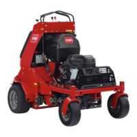
Note:Youmustloosenthenutsandboltsthat
securethetransmissionmountandtensioner
plateatbothsidesofthemachine.
g020261
Figure71
1.Hydromountingboltsand
nuts
4.6to12mm(1/4-1/2inch)
2.Nuts
5.Guardremovedforclarity
3.Adjustmentbolt
5.Turntheadjustmentbolttomovetransmission
adjustmentplatesandtransmission.
6.Whenthechainscanmoveupanddown6to12
mm(1/4to1/2inch),tightenthenutsonboth
sidesoftheadjustmentbolts.
7.Tightennutsandboltsthatsecurethehydro
mounting.
8.Adjustthetraction-controllinkage,referto
AdjustingtheTraction-ControlLinkage(page
50).
AdjustingtheDriveWheel
ChainTension
1.Shutofftheengine,engagetheparkingbrake,
removethekey,andwaitforallmovingpartsto
stopbeforeleavingtheoperatingposition.
2.Lifttherearofthemachineandsupportitusing
jackstands.
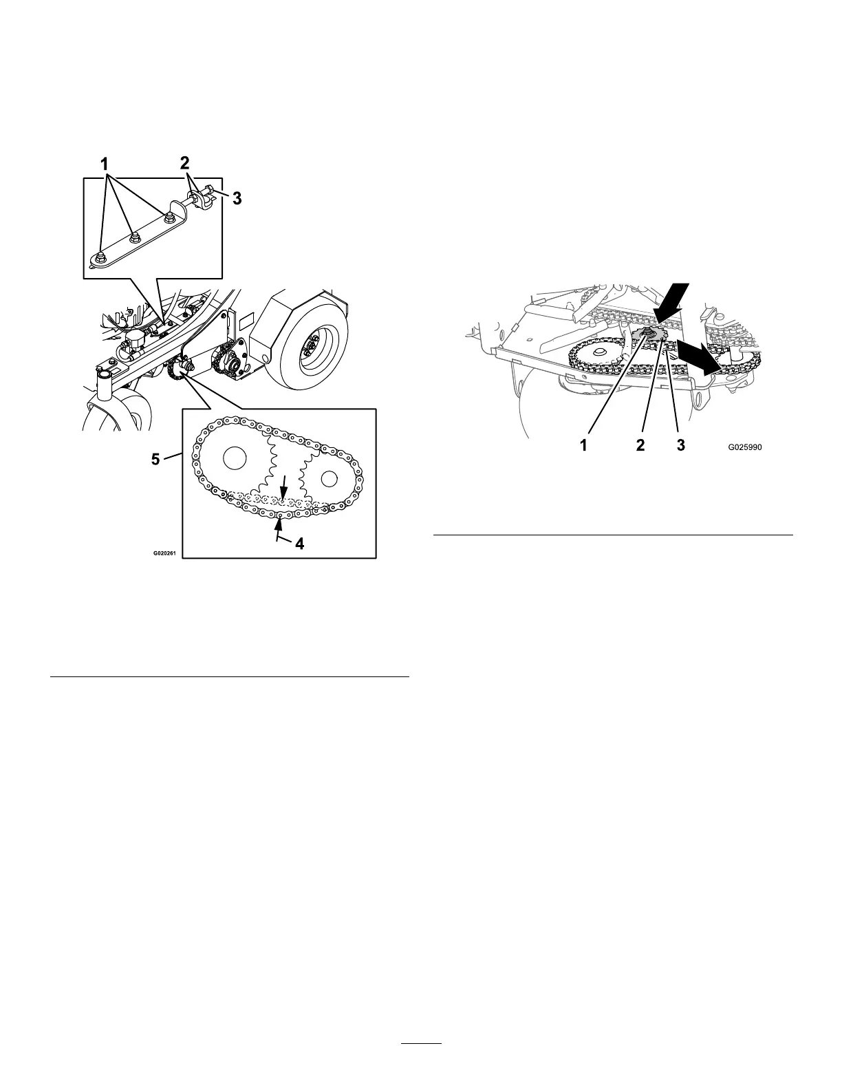
3.Checkthetensionofthedrive-wheelchains
(Figure72).
Note:Thechainsshouldmoveupanddown6
to12mm(1/4to1/2inch).
g025990
Figure72
1.Locknut3.Drive-wheelchain
2.Idlersprocket
4.Loosenthelocknutandcarriageboltthatsecure
theidlersprocket(Figure72).
5.Increaseordecreasechaintensionby
performingthefollowing:
•Pushdownandforwardonthesprocket
toincreasethechaintensionasshownin
Figure72.
•Liftupandbackonthesprockettodecrease
thechaintension.
6.T orquethelocknutto91to113N∙m(67to83
ft-lb).
7.Checkthechaintensionandifnecessaryrepeat
steps4through6untilyoucanmovethechain
upanddown6to12mm(1/4to1/2inch).
57