4. Push the mac hine to the desired location.
5. Set the parking brak e .
6. Close the b y-pass v alv es , but do not o v er tighten
them.
Important: Do not star t or operate the
machine with the by-pass v alv es open.
Dama ge to system may occur .
Transporting Machines
Use a hea vy-duty trailer or tr uc k to transpor t the
mac hine . Ensure that the trailer or tr uc k has
all necessar y brak es , lighting, and marking as
required b y la w . Please carefully read all the safety
instr uctions . Kno wing this infor mation could help
y ou, y our family , pets or b ystanders a v oid injur y .
T o transpor t the mac hine:
1. If using a trailer , connect it to the to wing
v ehicle and connect the safety c hains .
2. If applicable , connect the trailer brak es .
3. Load the mac hine onto the trailer or tr uc k.
4. Stop the engine , remo v e the k ey , set the brak e ,
and close the fuel v alv e .
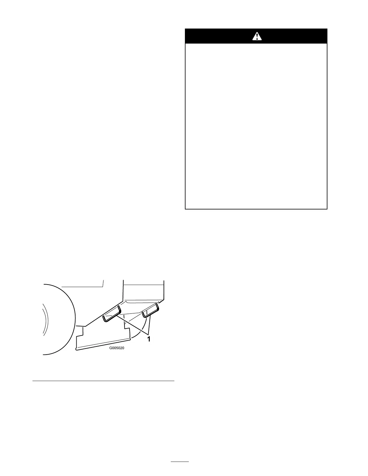
5. Use the metal tie do wn loops on the mac hine
to securely fasten the mac hine to the trailer
or tr uc k with straps , c hains , cable , or ropes
( Figure 12 ).
Figure 12
1. Traction unit tie down loop
Side Discharging or
Mulching the Grass
T his mo w er has a hing ed g rass deflector that
disperses clippings to the side and do wn to w ard
the turf .
W ithout the g rass deflector , discharge
co v er , or complete g rass catcher assembl y
mounted in place, y ou and other s ar e
exposed to blade contact and thr o wn de bris.
Contact with r otating mo w er blade(s) and
thr o wn de bris will cause injur y or death.
• Nev er r emo v e the g rass deflector fr om
the mo w er because the g rass deflector
r outes material do wn to w ard the turf.
If the g rass deflector is ev er dama ged,
r eplace it immediatel y .
• Nev er put y our hands or feet under the
mo w er .
• Nev er tr y to clear discharge ar ea or
mo w er blades unless y ou r elease the
bail and the po w er tak e of f (PT O) is
of f. R otate the ignition k ey to Of f. Also
r emo v e the k ey and pull the wir e(s) of f
the spar k plug(s).
Adjusting the Height-of-Cut
T he height-of-cut can be adjusted from 1 to
4-1/2 inc h (25 to 114 mm) in 1/4 inc h (6 mm)
increments . Adjustment is done b y relocating four
hair pin cotter pins in different hole location and
b y adding or remo ving spacers .
Note: All height-of-cut pins need at least one
spacer or damag e can occur to bushing if none
are used.
Note: All height-of-cut pins can use tw o spacers
maxim um.
1. Select hole in height-of-cut post and n umber
of spacers cor responding to the height-of-cut
desired ( Figure 13 ).
2. Using the lift handle , raise side of dec k and
remo v e hair pin cotter ( Figure 13 ).
3. Add or remo v e spacers if needed and then
align holes and inser t hair pin cotter ( Figure 13 ).
Note: Spare height-of-cut spacers ma y be
stored on posts and retained b y a hair pin cotter .
Important: All f our hair pin cotter pins
must be in the same hole location and with
the cor r ect n umber of spacer s f or a lev el
cut.
20