Note: Tire air pressure is critical in these
procedures . Mak e sure all tires ha v e cor rect
pressure .
1. Diseng ag e the PTO and set the parking brak e .
2. Stop the engine , remo v e the k ey , and w ait for
all mo ving par ts to stop before lea ving the
operating position. Disconnect the spark plug
wire(s) from the spark plug(s).
3. Adjust the tire pressure in the
rear tires to specifications; refer to
Dri v e System Maintenance , pag e 36 .
4. Chec k that the blades and spindle shafts are
not bent. R efer to Chec king for Bent Blades .
5. Set the height-of-cut to the 4 inc h (101.6 mm)
position. R efer to Adjusting the Height-Of-Cut
in Operation , pag e 14 .
6. P erfor m the ste ps in the follo wing sections
F rame Set Up , Chec king F ront-to-R ear Pitc h,
and Chec king Side-to-Side Lev eling .
Frame Set Up
Checking the Carrier Frame and
Engine Deck Alignment
Note: Misalignment can cause ex cess w ear on
the PTO dri v e belt.
1. Diseng ag e the PTO and set the parking brak e .
2. Stop the engine , remo v e the k ey , and w ait for
all mo ving par ts to stop before lea ving the
operating position.
3. Place a long straight edg e on top of the engine
dec k as sho wn in Figure 72 .
4. At the car rier frame cross c hannel, measure
the height at location A ( Figure 72 ). T his
measurement m ust be 1-5/16 inc h (33 mm),
plus or min us a 1/4 inc h (6 mm).
5. If the height at location A is not cor rect,
adjustment is needed.
6. Loosen the car rier frame mounting bolts on
both sides of the mac hine ( Figure 72 ).
7. Align the car rier frame and engine dec k to
matc h 1-5/16 inc h (33 mm), plus or min us a
1/4 inc h (6 mm) at location A ( Figure 72 ).
8. Tighten the car rier frame mounting bolts on
both sides of the mac hine .
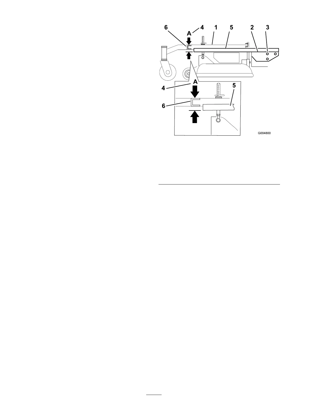
Figure 72
1. Carrier Frame
4. Location A, 1-5/16 inch (33
mm) ±1/4 inch (6 mm)
2. Top of engine deck 5. Straight edge
3. Carrier frame mounting
bolts
6. Carrier frame cross channel
Checking the Engine Deck Height
1. Diseng ag e the PTO and set the parking brak e .
2. Stop the engine , remo v e the k ey , and w ait for
all mo ving par ts to stop before lea ving the
operating position.
3. Adjust the tire pressure in the
rear tires to specifications; refer to
Dri v e System Maintenance , pag e 36 .
4. Measure engine dec k height at location A
( Figure 73 ).
52