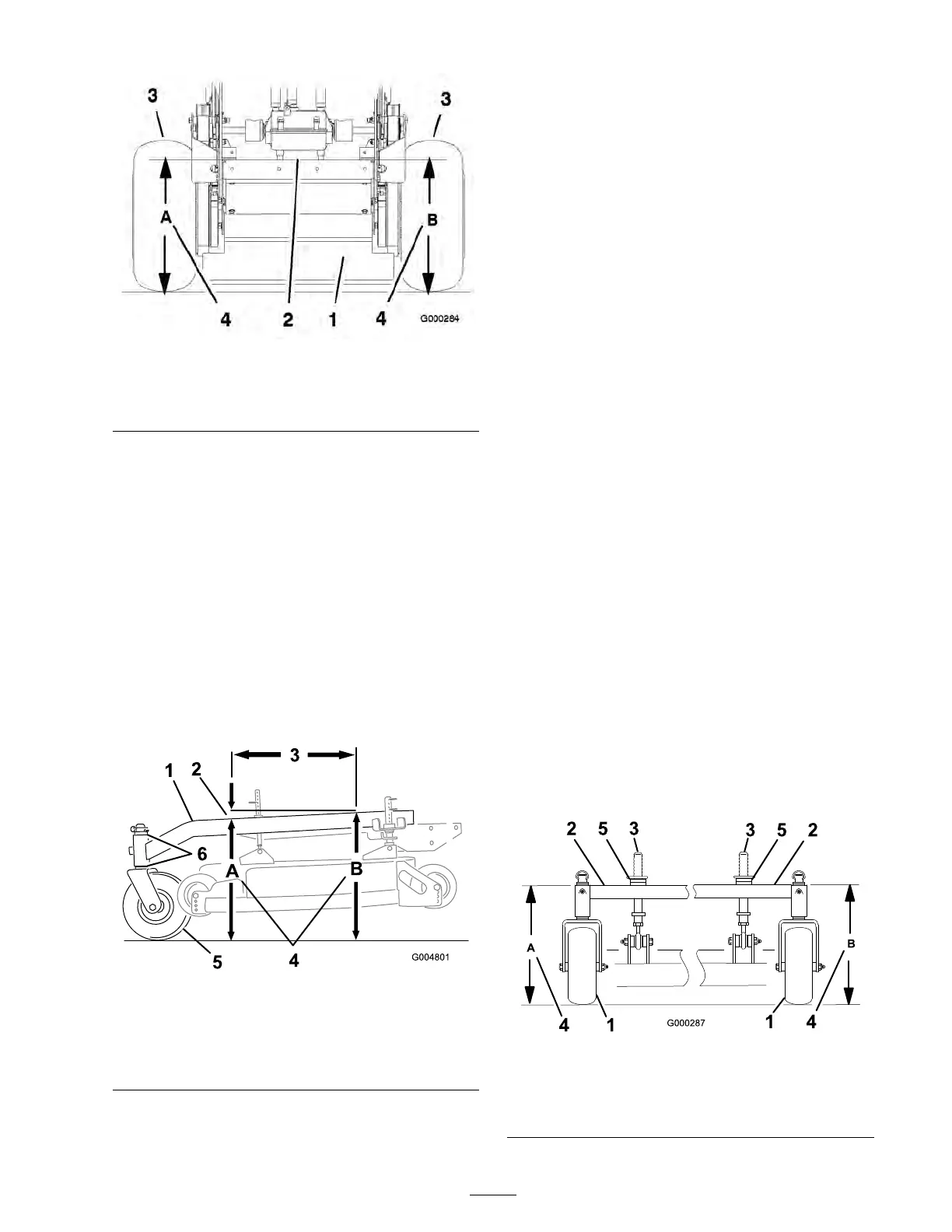
Figure 73
1. Back view of machine
3. Tires
2. Top of engine deck 4. Same height at locations A
and B
5. Measure engine dec k height at location B
( Figure 73 ).
6. If the height at location A and B are not the
same , c hang e tire pressure slightly to mak e
them the same .
Checking the Carrier Frame
Front-to-Rear Pitch
T he car rier frame m ust ha v e a pitc h betw een 1/8
inc h (3 mm) to 3/8 inc h (9 mm) o v er the length of
24 inc hes (61 cm) on the car rier frame ( Figure 74 ).
1. Measure out 24 inc hes (61 cm) on the car rier
frame ( Figure 74 ).
Figure 74
1. Carrier Frame
4. Height at locations A and B
2. 1/8 inch -3/8 inch (3-10
mm) pitch over 24 inch (61
cm) length
5. Caster Wheel
3. 24 inches (61 cm)
6. Caster spacers
2. Measure car rier frame height at location A
( Figure 74 ).
3. Measure car rier frame height at location B
( Figure 74 ).
4. T he height at location A m ust be an 1/8-3/8
inc h (3 mm -10 mm) lo w er than location B
( Figure 74 ).
5. If the car rier frame is not cor rect, mo v e caster
spacers to mak e it an 1/8-3/8 inc h (3 -10 mm)
pitc h ( Figure 74 ). Mo v e spacers from top or
bottom to mak e the cor rect pitc h.
6. T he tire pressure ma y also be adjusted slightly
to mak e an 1/8-3/8 inc h (3 -10 mm) pitc h.
Checking the Carrier Frame
Side-to-Side Height
T he car rier frame needs to be parallel side-to-side
from the g round.
1. Diseng ag e the PTO and set the parking brak e .
2. Stop the engine , remo v e the k ey , and w ait for
all mo ving par ts to stop before lea ving the
operating position.
3. Adjust the tire pressure in the
rear tires to specifications; refer to
Dri v e System Maintenance , pag e 36 .
4. Measure car rier frame height at location A
( Figure 75 ).
5. Measure car rier frame height at location B
( Figure 75 ).
6. If the car rier frame height is not the same
mo v e spacers from top or bottom of caster
wheel, to mak e it lev el. T he tire pressure ma y
also be adjusted slightly to mak e it lev el.
Figure 75
1. Caster Wheel 4. Same height at locations A
and B
2. Carrier Frame
5. Caster spacers
3. Front height-of-cut pins
53