6. Mak e sure the speed control lev er is in the
neutral position and the tires do not rotate .
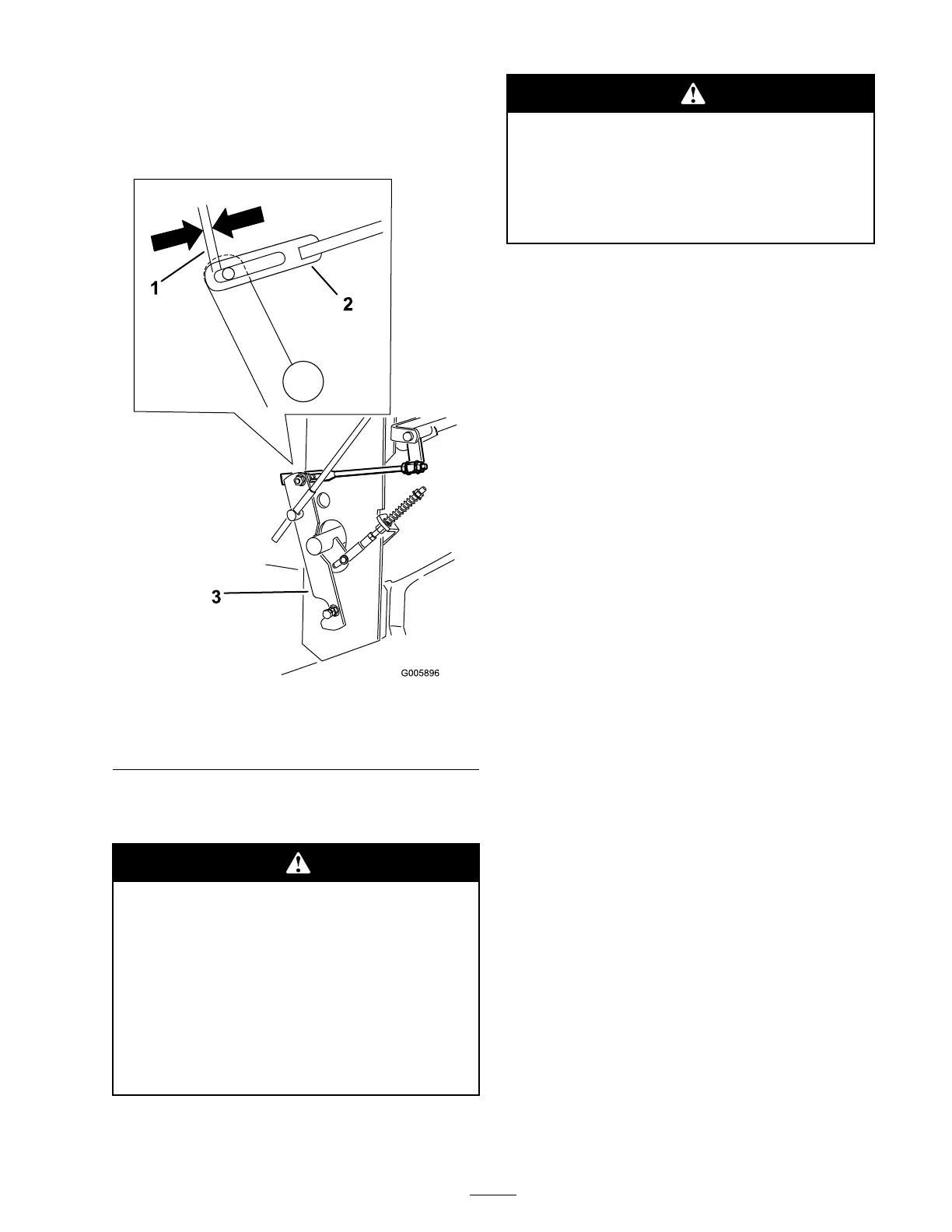
7. R e peat the linkag e adjustments if needed to
obtain neutral position.
Figure 51
1. Gap needs to be equal on
left and right side
3. Control arm
2. Hydro control linkage
Adjusting the Neutral Stud
Electrical system will not perf or m pr oper
safety shut of f with Operator Pr esence
Contr ol (OPC) lev er s held in place.
• Mak e sur e Operator Pr esence Contr ol
(OPC) lev er s ar e w or king when
adjustment is completed.
• Nev er operate this unit with Operator
Pr esence Contr ol (OPC) lev er s held in
place.
Mechanical or h y draulic jacks may f ail to
suppor t machine and cause a serious injur y .
• Use jack stands when suppor ting
machine.
• Do not use h y draulic jacks.
1. With the mac hine on jac k stands , place the
speed control lev er in the neutral position.
2. Hold the OPC lev ers do wn.
Note: T he OPC lev ers m ust be held do wn
whenev er the speed control lev er is out of the
neutral position or the engine will kill.
3. Adjust the left and right neutral stud until the
clevis pin in the y ok e touc hes the bac k end of
the slot in the control ar m ( Figure 52 ).
4. Mo v e the speed control lev er to the full
forw ard position.
5. Squeeze one dri v e lev er until an increased
resistance is felt. T his is neutral position. T his
is where the clevis pin in the y ok e comes to the
bac k end of the slot in the control ar m brac k et.
Note: Mak e sure y ou ha v e not reac hed the
end of the neutral loc k slot. If y ou ha v e ,
shor ten the control lev er linkag e . R efer to
Adjusting the Control R od.
6. If the wheel tur ns while holding the dri v e lev er
in neutral, the neutral stud needs to be adjusted
( Figure 52 ). If wheel stops then g o to .
7. Loosen the n ut ag ainst the y ok e ( Figure 52 ).
8. Adjust the adjustment stud until the respecti v e
dri v e wheel stops while holding the dri v e in
the neutral position (increased resistance)
( Figure 52 ).
9. T ur n the adjusting bolt appro ximately 1/4
tur n cloc kwise if the wheel is tur ning in
rev erse or tur n the bolt appro ximately 1/4
tur n counter -cloc kwise if the wheel is tur ning
forw ard ( Figure 52 ).
10. R elease the dri v e lev er to the forw ard dri v e
position and squeeze bac k into the neutral
position. Chec k to see if the wheel stops . If
not, re peat the abo v e adjustment procedure .
11. After adjustments are made , tighten the n uts
ag ainst the y ok es .
12. R e peat this procedure for the opposite side .
41