Figure 49
1. Speed control lever
3. spring
2. Rear pivot spring
15. Tighten the front n ut on left h y dro control
linkag e sho wn in Figure 48 .
Adjusting the Right Side Linkage
1. With the mac hine on jac k stands , place the
speed control lev er in the neutral position.
2. Place the right dri v e lev er in the full forw ard
position.
3. Hold the OPC lev ers do wn.
Note: T he OPC lev ers m ust be held do wn
whenev er the speed control lev er is out of the
neutral position or the engine will kill.
4. Adjust the right side linkag e b y tur ning the
quic k trac k knob countercloc kwise until the
tire begins to rotate forw ard ( Figure 50 ).
5. T ur n the knob cloc kwise a 1/4 of a tur n at a
time . T hen mo v e the speed control forw ard
and bac k to neutral. R e peat this until right
wheel stops rotating forw ard ( Figure 50 ).
6. T he spring that k ee ps tension on the knob
should nor mally not need adjustment.
Ho w ev er if an adjustment is needed, adjust the
length of spring to 1 inc h (26 mm) betw een
the w ashers ( Figure 50 ).
7. Adjust the spring length b y tur ning the n ut at
the front of spring ( Figure 50 ).
8. After adjusting the right h y dro control linkag e ,
mo v e the speed control lev er forw ard and then
bac k to the neutral position.
9. Mak e sure the speed control lev er is in the
neutral position and the tire does not rotate .
10. R e peat adjustment if needed.
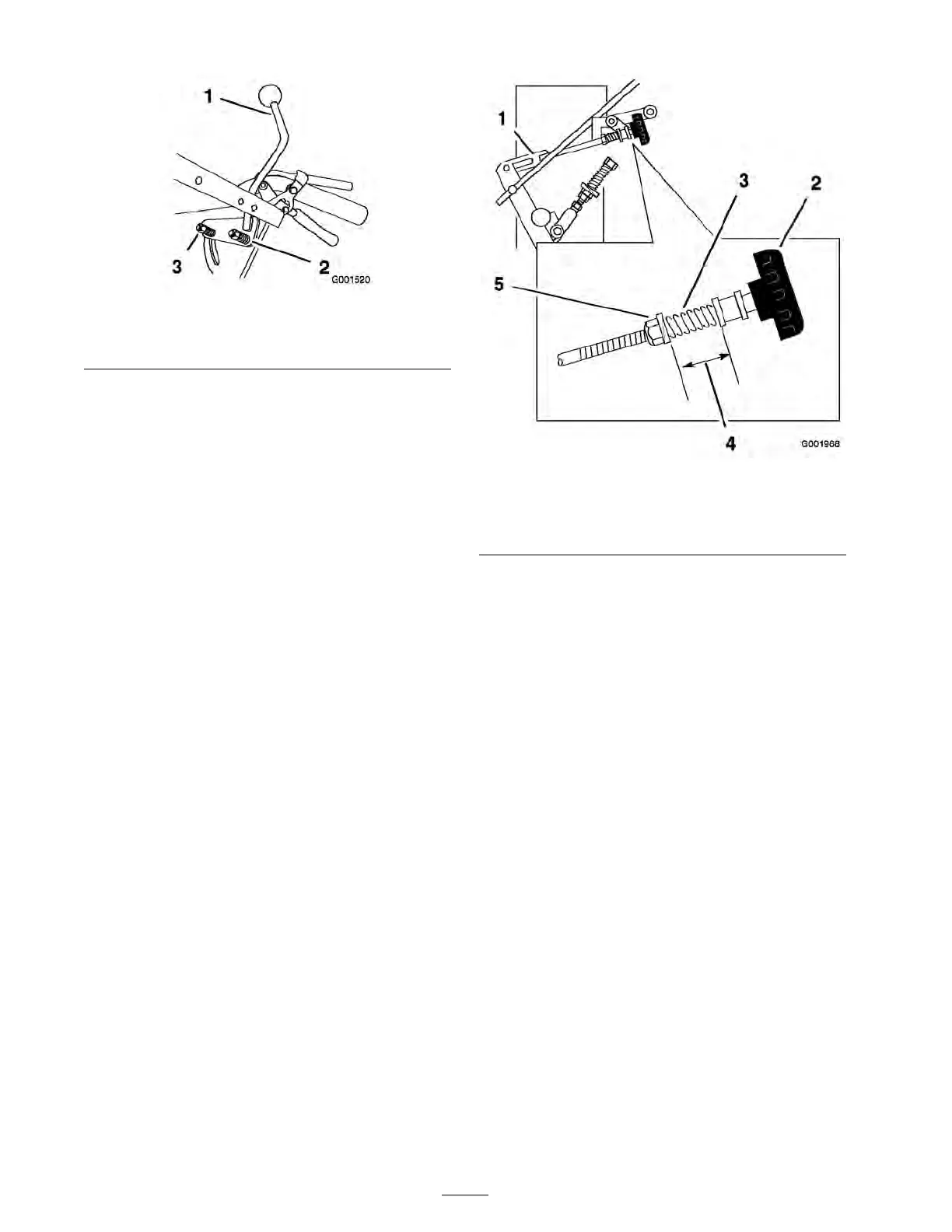
Figure 50
1. Hydro control linkage
4. 1 inch (26 mm)
2. Quick track knob 5. Nut in front of spring
3. Spring
Checking and Adjusting the Left and
Right Speed Control Linkage Travel
T he speed control lev er has extra tra v el a v ailable
to ensure full pump eng ag ement.
It is impor tant to ha v e the same amount of tra v el
for both the left and right speed control linkag es .
1. Mo v e the speed control lev er to the full speed
forw ard position.
2. Measure the g ap as sho wn in Figure 51 for
both the left and right sides . No adjustment is
needed if they are equal.
3. If needed, adjust the right side linkag e b y
tur ning the quic k trac k knob until the g ap in
Figure 51 matc hes the left side ( Figure 50 ).
4. If needed, adjust the left side linkag e b y
adjusting the front and bac k swi v el n uts until
the g ap in Figure 51 matc hes the right side
( Figure 48 ).
5. After adjusting the h y dro control linkag e , mo v e
the speed control lev er forw ard and then bac k
to the neutral position.
40