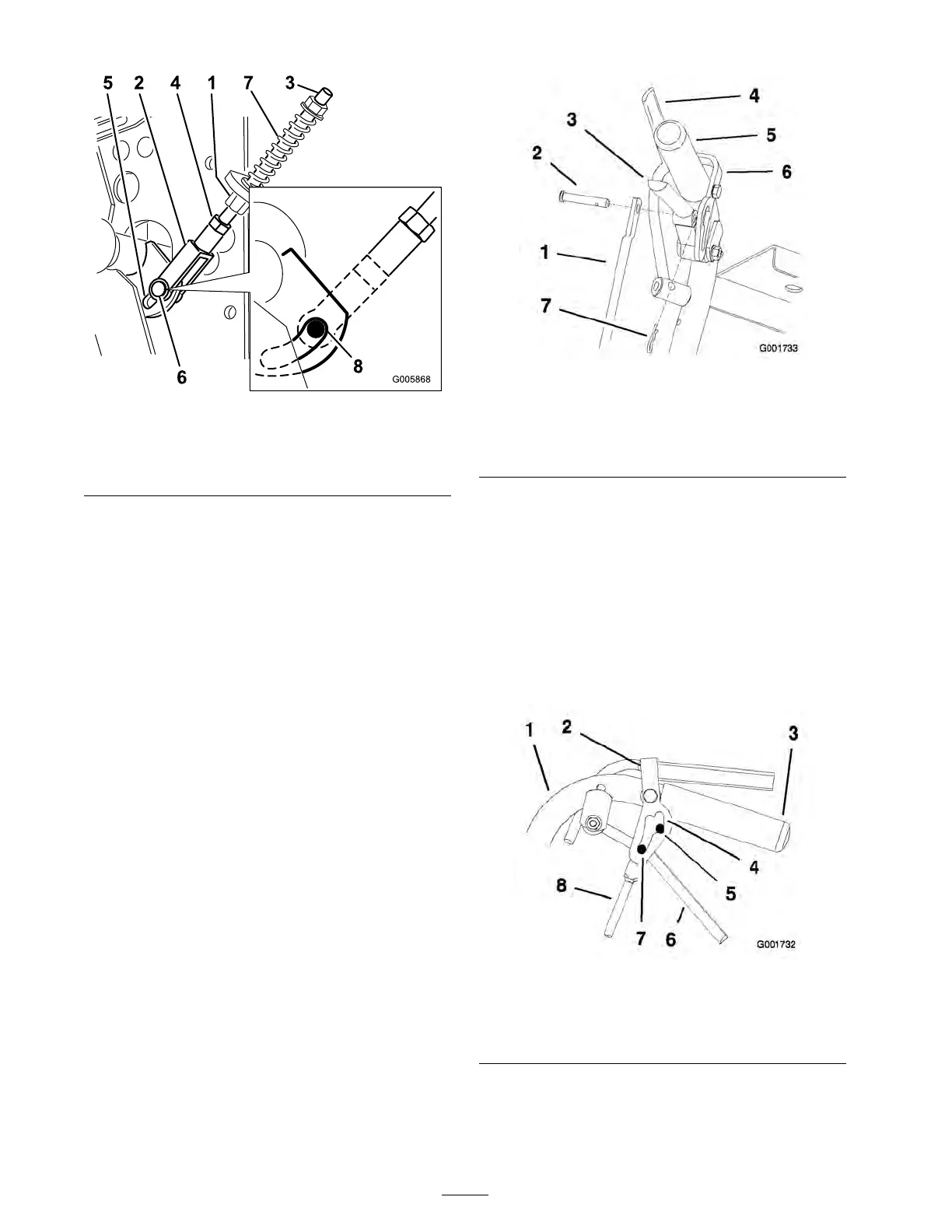
Figure 52
1. Neutral control linkage 5. Slot in control arm bracket
2. Yoke 6. Clevis pin
3. Neutral stud
7. Spring
4. Nut
8. Back end of slot
Adjusting the Control Rod
Checking the Control Rod
1. With rear of mac hine still on jac k stands and
engine r unning at full throttle , mo v e the speed
control lev er to the medium speed position.
Note: T he OPC lev ers m ust be held do wn
whenev er the speed control lev er is out of the
neutral position or the engine will kill.
2. Mo v e the respecti v e dri v e lev er upw ard until it
reac hes the neutral position and eng ag e neutral
loc ks .
3. If the tire rotates in either direction, the length
of the control rod will need to be adjusted.
Adjusting the Control Rod
1. Adjust the rod length b y releasing the dri v e
lev er and remo ving the hair pin cotter pin and
clevis pin. R otate the rod in the rod fitting
( Figure 53 ).
2. Lengthen the control rod if the tire is tur ning
in rev erse and shor ten the rod if the tire is
tur ning forw ard.
3. R otate the rod sev eral tur ns if the tire is
rotating fast. T hen, adjust the rod in 1/2 tur n
increments .
4. Place the clevis pin into the dri v e lev er
( Figure 53 ).
Figure 53
1. Control rod 5. Left handle shown
2. Clevis pin 6. Neutral lock
3. Drive lever
7. Hairpin cotter pin
4. Operator Presence Control
lever (OPC)
5. R elease and eng ag e neutral loc k c hec king that
the tire does not rotate ( Figure 54 ). Contin ue
this process until the tire does not rotate .
6. Install the hair pin cotter pin betw een the dri v e
lev ers and the neutral loc ks and into the clevis
pins ( Figure 53 ).
Note: Mak e sure the clevis pins are inser ted
into the neutral loc ks .
7. R e peat this adjustment for the opposite side .
Figure 54
1. Handle 5. Neutral position
2. Neutral lock 6. Drive lever
3. Handle 7. Full speed forward
4. Neutral lock slot 8. Control rod
Adjusting the Tracking
1. R emo v e mac hine from any jac k stands .
42