A blade that is bent or dama ged could
br eak apar t and could seriousl y injur e or
kill y ou or bystander s.
• Al w ays r eplace bent or dama ged
blade with a new blade.
• Nev er file or cr eate shar p notches in
the edges or surf aces of blade.
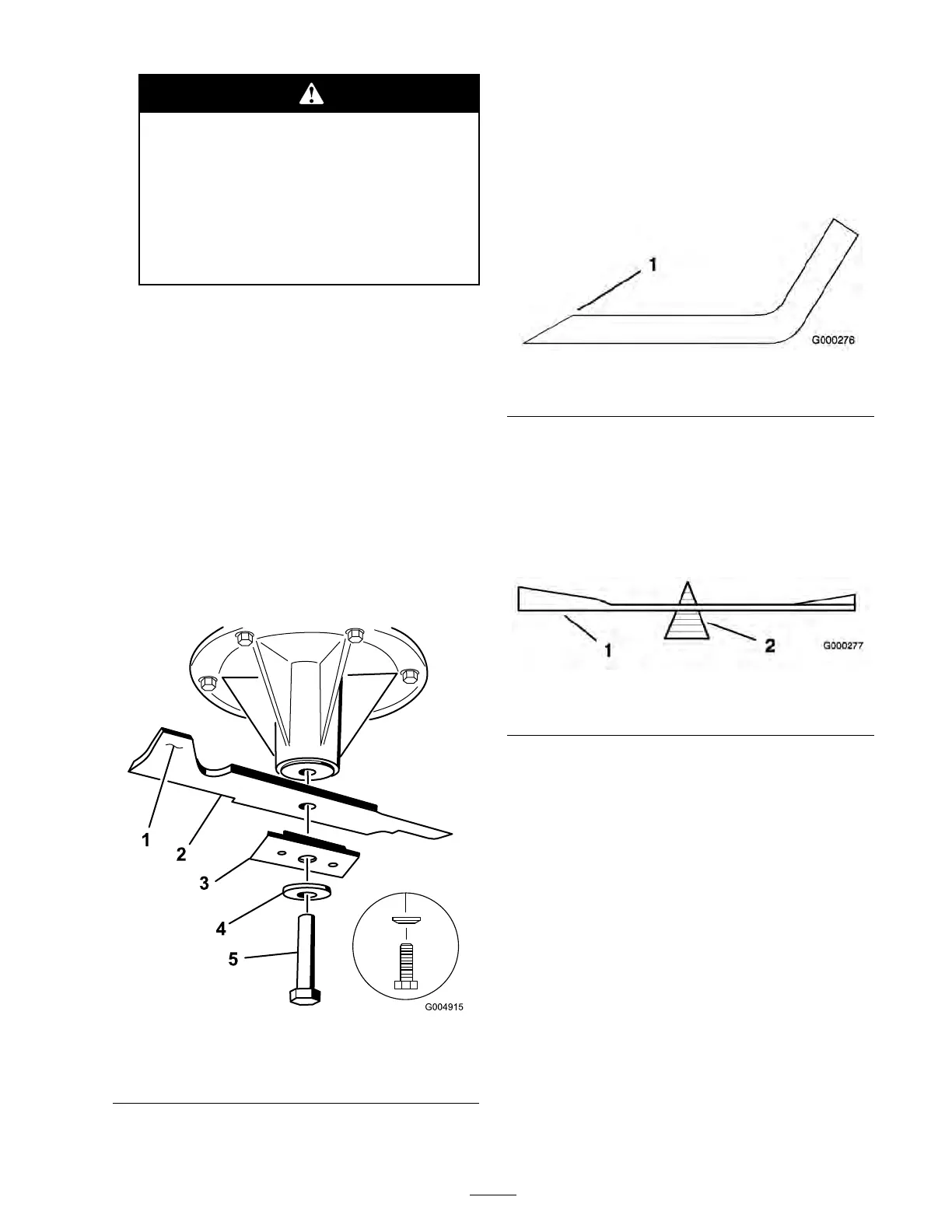
Removing the Blades
Blades m ust be re placed if a solid object is hit,
if the blade is out of balance or is bent. T o
ensure optim um perfor mance and contin ued
safety confor mance of the mac hine , use g en uine
T oro re placement blades . R e placement blades
made b y other man ufacturers ma y result in
non-confor mance with safety standards .
1. Hold the blade end using a rag or
thic kly-padded glo v e .
2. R emo v e the blade bolt, cur v ed w asher , blade
stiffener , and blade from the spindle shaft
( Figure 69 ).
Figure 69
1. Sail Area of Blade 4. Curved washer
2. Blade 5. Blade Bolt
3. Blade stiffener
Sharpening the Blades
1. Use a file to shar pen the cutting edg e at both
ends of the blade ( Figure 70 ). Maintain the
original angle . T he blade retains its balance if
the same amount of material is remo v ed from
both cutting edg es .
Figure 70
1. Sharpen at original angle
2. Chec k the balance of the blade b y putting it on
a blade balancer ( Figure 71 ). If the blade sta ys
in a horizontal position, the blade is balanced
and can be used. If the blade is not balanced,
file some metal off the end of the sail area only
( Figure 69 ). R e peat this procedure until the
blade is balanced.
Figure 71
1. Blade 2. Balancer
Installing the Blades
1. Install the blade onto the spindle shaft
( Figure 69 ).
Important: T he sail par t of the blade
must be pointing up w ard, to w ard the
inside of the mo w er to ensur e pr oper
cutting ( Figur e 69 ).
2. Install the blade , stiffener , cur v ed w asher , and
blade bolt ( Figure 69 ).
3. T or que the blade bolt to 85-110 ft-lb (115-140
N•m).
Correcting the Mower
Quality of Cut
If one dec k blade cuts lo w er than the other , cor rect
as follo ws .
51