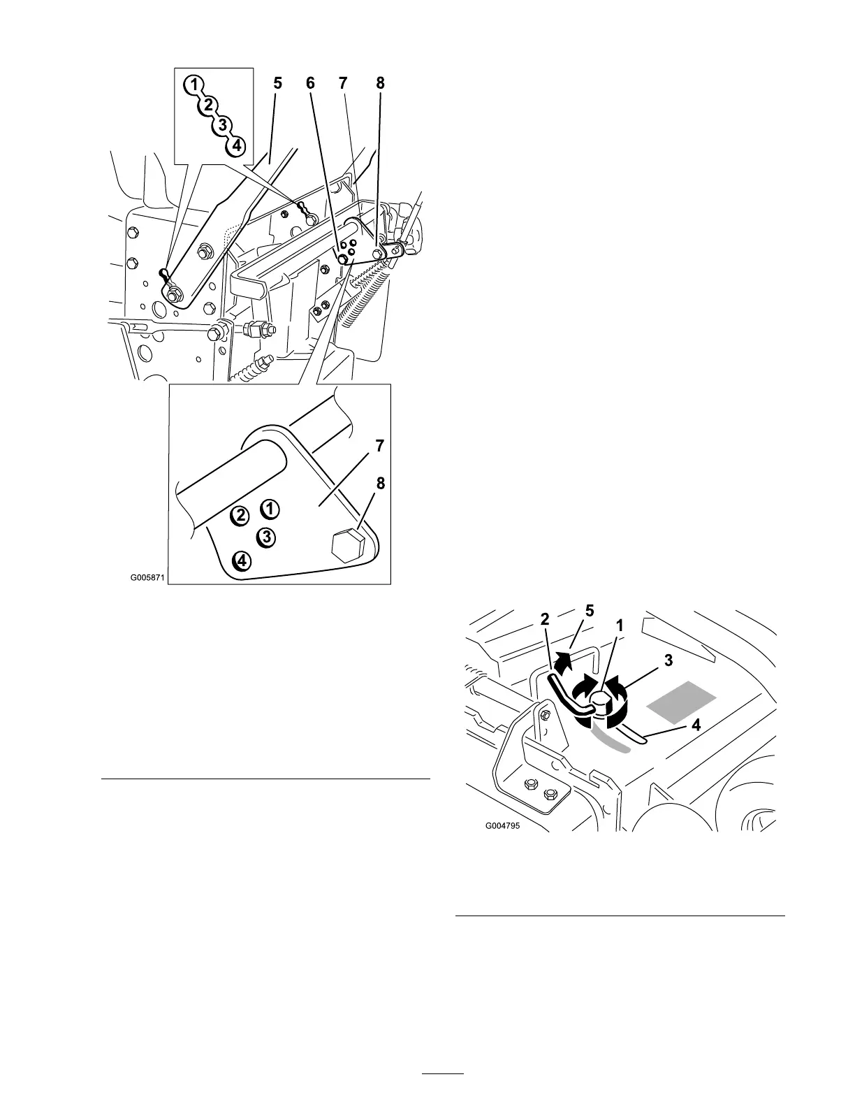
Figure 19
1. Match the hole in speed
control crank with handle
height
5. Handle
2. Match the hole in speed
control crank with handle
height
6. Front bolt
3. Match the hole in speed
control crank with handle
height
7. Speed control crank
4. Match the hole in speed
control crank with handle
height
8. Back bolt
11. Adjust the swi v el on the speed control rod and
tighten the n uts ag ainst the swi v el ( Figure 17 ).
12. Adjust the control rod length b y rotating the
control rod in the rod fitting ( Figure 17 ).
13. Install the hair pin cotter betw een dri v e
lev ers and neutral loc ks and into clevis pins
( Figure 16 ).
Note: Mak e sure the clevis pins are inser ted
into the neutral loc ks .
14. P erfor m the h y draulic linkag e adjustments
when the handle height is c hang ed; refer
Hy draulic Linkag e Adjustments .
Adjusting the Flow Bafe
T he mo w er disc harg e flo w can be adjusted for
different types of mo wing conditions . P osition the
cam loc k and baffle to gi v e the best quality of cut.
1. Diseng ag e the PTO , mo v e the motion control
lev ers to the neutral loc k ed position and set
the parking brak e .
2. Stop the engine , remo v e the k ey , and w ait for
all mo ving par ts to stop before lea ving the
operating position.
3. T o adjust the cam loc k, swing the lev er up to
loosen the cam loc k ( Figure 20 ).
4. Adjust the baffle and cam loc k in the slot to
the desired disc harg e flo w .
5. Swing the lev er bac k o v er to tighten the baffle
and cam loc k ( Figure 20 ).
6. If the cam does not loc k the baffle into place
or it is too tight, loosen the lev er and then
rotate the cam loc k. Adjust the cam loc k until
the desired loc king pressure is ac hiev ed.
Figure 20
1. Cam lock
3. Rotate cam to increase or
decrease locking pressure
2. Lever
4. Slot
Positioning the Flow Bafe
T he follo wing figures are only recommendations
for use . Adjustments will v ar y b y g rass type ,
moisture content, and height of g rass .
23