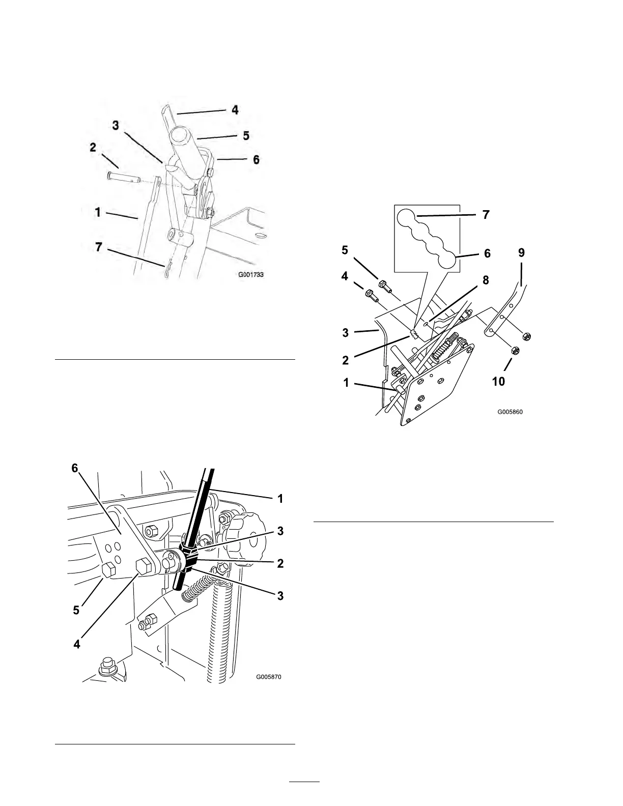
1. R emo v e the hair pin cotter pins and clevis
pins from the dri v e lev ers and neutral loc ks
( Figure 16 ).
Figure 16
1. Control rod 5. Left handle shown
2. Clevis pin 6. Neutral lock
3. Drive lever
7. Hairpin cotter pin
4. Operator Presence Control
lever (OPC)
2. Loosen the n uts holding the swi v el connected
to the speed control crank ( Figure 17 ).
3. R emo v e the front bolt from speed control
crank ( Figure 17 ).
4. Loosen the bac k bolt holding the speed control
rod to the speed control crank ( Figure 17 ).
Figure 17
1. Speed control rod 4. Front bolt
2. Swivel 5. Back bolt
3. Nut
6. Speed control crank
5. Loosen the upper flang e bolts (3/8 x 1-1/4
inc hes) and flang e n ut securing the handle to
the rear frame ( Figure 18 ).
6. R emo v e the lo w er flang e bolts (3/8 x 1 inc h)
and flang e n uts securing the handle to the rear
frame ( Figure 18 ).
7. Pi v ot handle to desired operating position and
install lo w er flang e bolts (3/8 x 1 inc h)and
flang e n uts into mounting holes . Tighten all
flang e bolts .
Figure 18
1. Control rod tting 6. High position
2. Lower mounting holes
7. Lower position
3. Rear frame 8. Upper mounting hole
4. Lower ange bolt (3/8 x 1
inch)
9. Handle
5. Upper ange bolt (3/8 x
1-1/4 inches)
10. Flange nut (3/8 inch)
8. Note what hole the handle w as installed
( Figure 19 ).
9. Install the front bolt into the cor responding
hole that w as used for the handle height (i.e .
with the handle set to hole n umber 3, the front
bolt in the speed control crank needs to be set
to hole n umber 3) ( Figure 19 ).
10. Tighten the bac k bolt holding the speed control
rod to the speed control crank ( Figure 19 ).
22