3. Raise the rear of the mac hine onto jac k stands
high enough to raise the dri v e wheels off of
the g round.
4. Diseng ag e the parking brak e .
5. Star t the engine and mo v e the throttle ahead to
the full throttle position.
6. Press and hold the OPC lev ers do wn.
Note: T he OPC lev ers m ust be held do wn
whenev er the speed control lev er is out of the
neutral position or the engine will kill.
7. Place the left dri v e lev er in the full forw ard
position.
8. Place the speed control lev er in the neutral
position.
Electrical system will not perf or m pr oper
safety shut of f with Operator Pr esence
Contr ol (OPC) lev er s f astened in place.
• Mak e sur e Operator Pr esence Contr ol
(OPC) lev er s ar e w or king when
adjustment is completed.
• Nev er operate this unit with Operator
Pr esence Contr ol (OPC) lev er s
f astened in place.
9. Loosen the front adjusting n ut on left h y dro
control linkag e as sho wn in Figure 48 .
10. T ur n the left rear adjusting n ut
counter -cloc kwise until wheel rotates
forw ard ( Figure 48 ).
11. T ur n the rear adjusting n ut cloc kwise 1/4 of a
tur n at a time . T hen mo v e the speed control
lev er forw ard and bac k to neutral. R e peat
this until left wheel stops rotating forw ard
( Figure 48 ).
Note: Mak e sure flat par t of the linkag e
is per pendicular to the pin of the swi v el
( Figure 48 ).
12. After adjusting the left h y dro control linkag e ,
mo v e the speed control lev er forw ard and then
bac k to the neutral position.
13. Mak e sure the speed control lev er is in the
neutral position and the tire does not rotate .
14. R e peat the adjustment if needed.
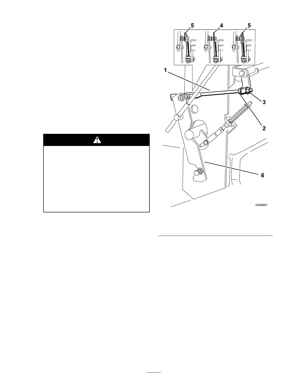
Figure 48
1. Hydro control linkage
4. Correct position
2. Front adjusting nut
5. Incorrect position
3. Rear adjusting nut 6. Control arm
Note: If inconsistent neutral occurs , c hec k
to be sure both springs are properly tightened
on the speed control lev er under the console ,
especially the rear pi v ot spring . R e peat abo v e
adjustments if necessar y ( Figure 49 ).
39