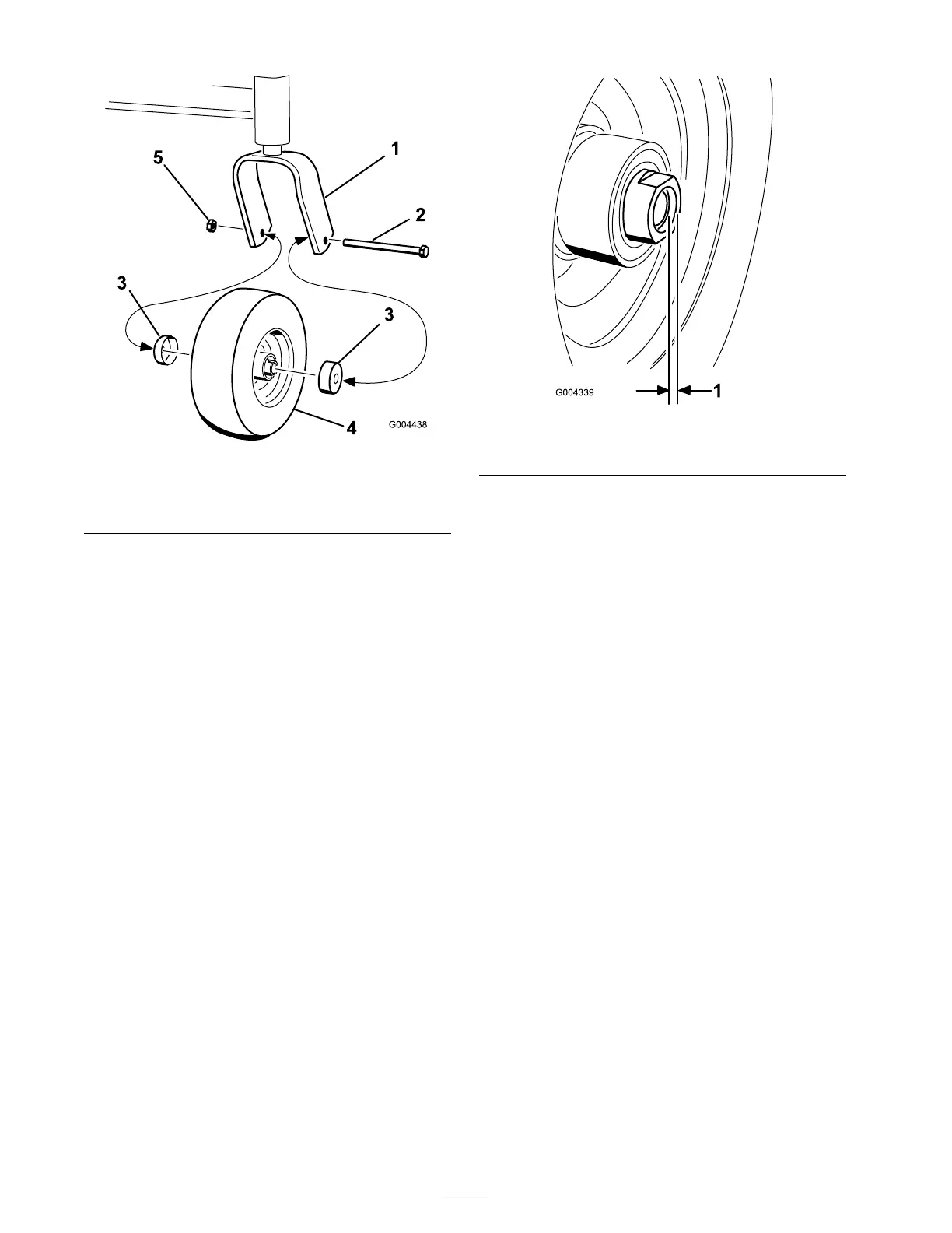
Figure 28
1. Caster fork 4. Caster wheel
2. Bolt
5. Nut
3. Seal guard
6. R emo v e one of the spacer n uts (with wrenc h
flats) from the axle ( Figure 30 ).
Note: T hread loc king adhesi v e has been
applied to the spacer n uts .
7. R emo v e the axle without remo ving the
opposite spacer n ut ( Figure 30 ).
8. R emo v e the seals and inspect the bearings
for w ear or damag e . R e place the bearings if
needed.
9. P ac k the bearings with g eneral pur pose g rease .
10. Inser t the bearing and a new seal into the
wheel ( Figure 30 ).
Note: Do not install the n ut all the w a y onto
the axle .
11. If both spacer n uts w ere remo v ed from the
axle , apply thread loc king adhesi v e to the
spacer n ut. Install the spacer n uts onto the axle
lea ving an 1/8 inc h (3mm) of the n ut past the
axle ( Figure 29 ).
Figure 29
1. 1/8 inch (3 mm) of the nut past the axle
12. Install the assembled n ut and axle into the
wheel on the side with the bearing and a new
seal ( Figure 30 ).
13. Place the wheel with the open end facing
up and fill the area inside the wheel with
m ulti-pur pose g rease .
14. Install the second bearing and a new seal into
the wheel ( Figure 30 ).
15. Apply thread loc king adhesi v e to the second
spacer n ut and install it onto the axle with the
wrenc h flats facing outw ard.
16. T or que the spacer n ut to 75-80 in-lb (8-9 N ⋅ m)
then loosen it and tor que it to 20–25 in-lb (2-3
N ⋅ m). Mak e sure the axle does not extend past
either n ut ( Figure 29 ).
17. Install the seal guards o v er the wheel hubs and
inser t the wheel into the caster fork ( Figure 28 ).
18. Install the caster bolt and tighten the n ut
( Figure 28 ).
Important: Check the bearing
adjustment often to pr ev ent seal and
bearing dama ge. Spin the caster tir e. T he
tir e should not spin fr eel y mor e than 1 to 2
r ev olutions or ha v e an y side-to-side play
betw een the caster f or k. If the wheel spins
fr eel y , adjust the torque on the spacer n ut
until ther e is a slight amount of dra g .
28