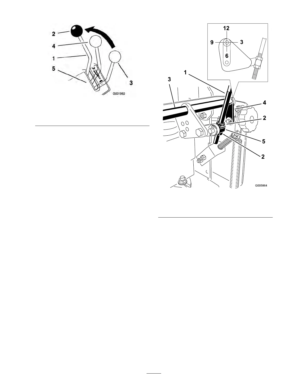
Figure 44
1. Speed control lever 4. Medium speed position
2. Full speed position 5. Control panel
3. Neutral position
5. Chec k the orientation of the tabs on the ends
of the speed control crank. T hese tabs should
be pointing straight do wn at the 6 o’cloc k
position appro ximately ( Figure 45 ).
6. If adjustment is needed, loosen the n uts on
both sides of the swi v el on the speed control
rod ( Figure 45 ).
7. Adjust the swi v el until the tabs are at the
6 o’cloc k position ( Figure 45 ).
8. Tighten the n uts on both sides of the swi v el
( Figure 45 ).
Figure 45
1. Speed control rod
4. Tabs, 6 o’clock position
2. Jam nut
5. Swivel
3. Speed control crank
9. Pull the speed control lev er bac k to neutral.
10. Chec k the tra v el of the shift lev er in the control
panel slot. T he shift lev er tra v el should be
appro ximately centered in the control panel
slot ( Figure 44 ).
11. If needed, adjust the swi v el on the speed
control rod to center the shift lev er tra v el
( Figure 45 ).
12. With the speed control lev er in the neutral
position, c hec k to mak e sure the safety switc h
is de pressed and there is an 1/8 to 1/4 inc h (3
to 6 mm) space betw een the actuating tab and
the safety switc h ( Figure 46 )..
37