If the engine has been r unning , pr essuriz ed
hot coolant can escape when the radiator
cap is r emo v ed and cause bur ns.
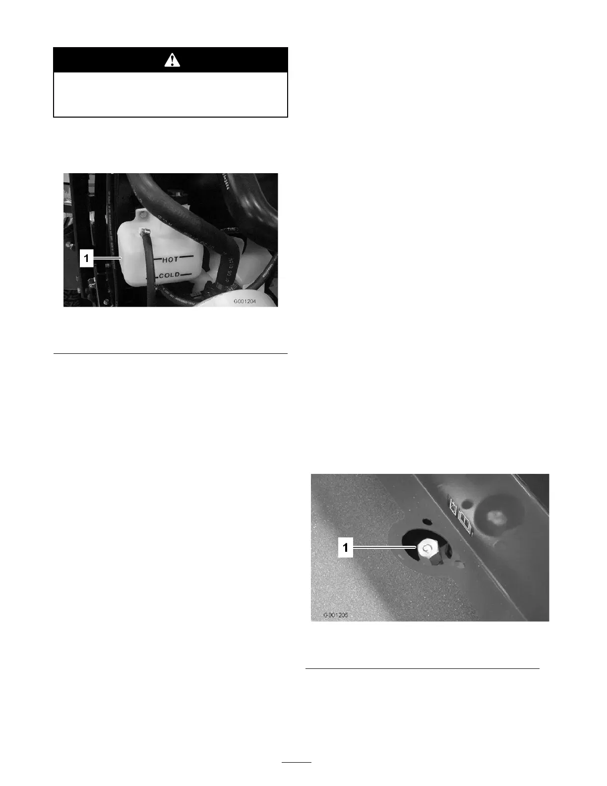
1. Chec k the lev el of the coolant in the expansion
tank ( Figure 21 ). T he coolant lev el should be
betw een the marks on the side of the tank.
Figure 21
1. Expansion tank
2. If coolant lev el is lo w , remo v e expansion tank
cap and re plenish the system. Do not o v erfill .
3. Install expansion tank cap .
Checking the Hydraulic
System
T he mac hines reser v oir is filled at the factor y
with appro ximately 5 quar ts (4.7 l) of high quality
h y draulic fluid. Chec k the lev el of the h y draulic
fluid before the engine is first star ted and daily
thereafter . T he recommended re placement fluid is
as follo ws:
Toro Premium All Season Hydraulic Fluid
(Available in 5 gallon pails or 55 gallon drums. See
parts catalog or Toro distributor for part numbers.)
Alter nate fluids: If the T oro fluid is not a v ailable ,
other fluids ma y be used pro vided they meet all
the follo wing material proper ties and industr y
specifications . W e do not recommend the use
of synthetic fluid. Consult with y our lubricant
distributor to identify a satisfactor y product
Note: T oro will not assume responsibility for
damag e caused b y improper substitutions , so use
only products from re putable man ufacturers who
will stand behind their recommendation.
Material Properties:
Viscosity, ASTM D445
cSt @ 40°C 44 to 48
cSt @ 100°C 9.1 to 9.8
Viscosity Index ASTM
D2270
140 to 152
Pour Point, ASTM D97
-34°F to -46°F
Industry Specications:
API GL-4, AGCO Poweruid 821 XL, Ford
New Holland FNHA-2-C-201.00, Kubota UDT,
John Deere J20C, Vickers 35VQ25, and Volvo
WB-101/BM
Note: Many h y draulic fluids are almost colorless ,
making it difficult to spot leaks . A red dye additi v e
for the h y draulic system oil is a v ailable in 2/3 oz.
(20 ml) bottles . One bottle is sufficient for 4-6
g al (15-22 1) of h y draulic oil. Order par t n umber
44-2500 from y our authorized T oro distributor .
1. P osition mac hine on a lev el surface . Place
all control in neutral position and star t the
engine . R un engine at lo w est possible RPM to
purg e the system of air . Do not enga ge the
PT O . Cycle steering wheel sev eral times fully
to the left and right. Raise the dec k to extend
lift cylinders , aiming steering wheels straight
forw ard and stop the engine .
2. R emo v e dipstic k cap ( Figure 22 ) from filler
nec k and wipe it with a clean rag . Screw
dipstic k cap fing er -tight onto filler nec k; then
remo v e it and c hec k lev el of fluid. If lev el is not
within 1/2 inc h (13 mm) from the g roo v e in
the dipstic k, add enough high quality h y draulic
fluid to raise lev el to g roo v e mark. Do not
o v erfill.
Figure 22
1. Hydraulic system reservoir uid/add dipstick cap
3. T hread dipstic k fill cap fing er -tight onto filler
nec k. It is not recommended to tighten cap
with a wrenc h.
4. Chec k all hoses and fittings for leaks .
30