Important: Do not push or to w the
machine f aster than 2 to 3 mph because the
transmission may be dama ged. If the machine
must be mo v ed a considera ble distance,
transpor t it on a tr uck or trailer . W henev er the
machine is pushed or to w ed, the by-pass v alv e
must be open.
1. Loosen the knob and remo v e the access
co v er at the rear of the seat mounting plate
( Figure 29 ).
Figure 29
1. Access cover knob
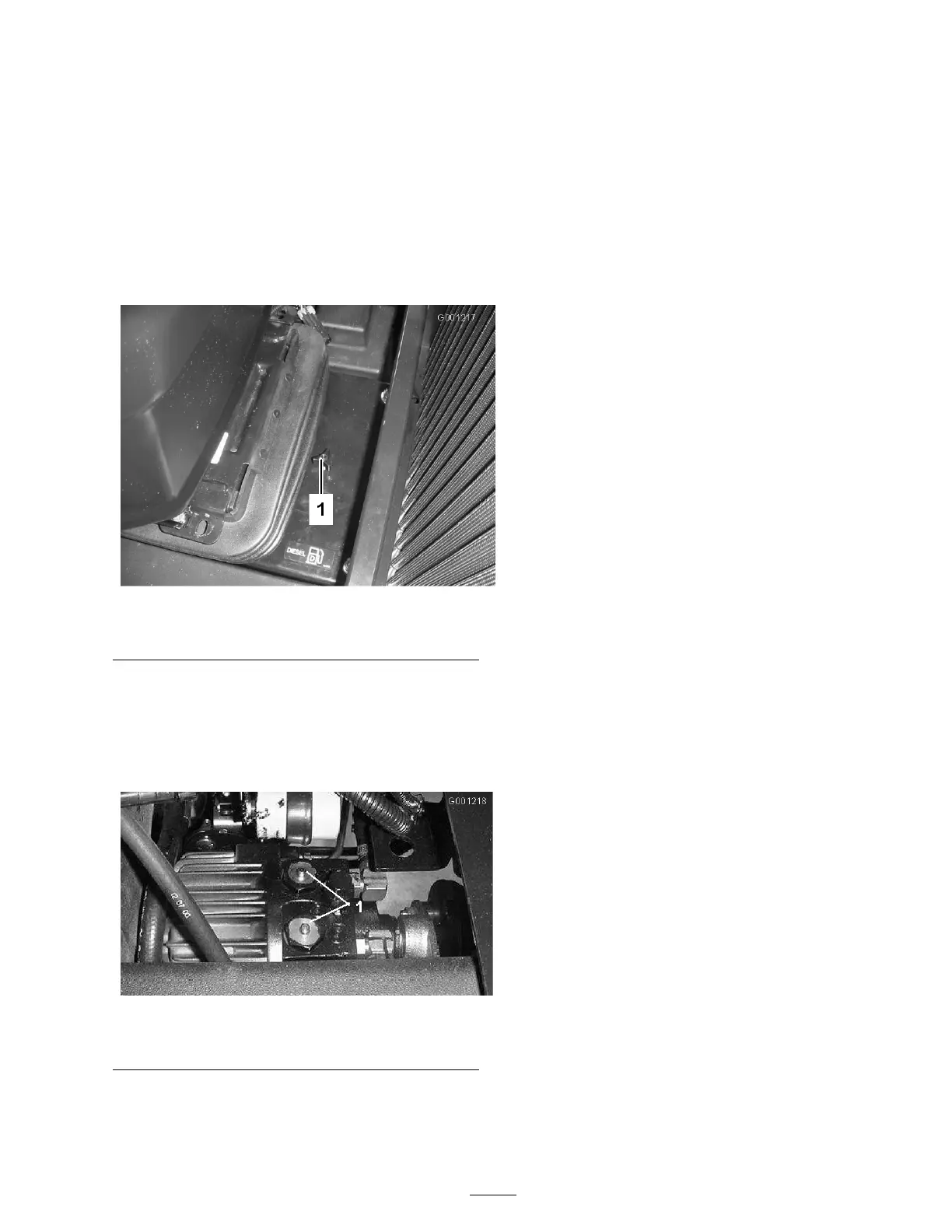
2. Press and hold the pins located in the center
of the 2 c hec k v alv e assemblies in the top of
the transmission ( Figure 30 ) while pushing or
to wing the mac hine . Figure 30 is sho wn with
seat and seat mounting plate remo v ed.
Figure 30
1. Transmission check valve by-pass pins (2)
3. Star t the engine momentarily after the re pairs
are completed and mak e sure the pins are in
the full diseng ag ed (fully up) position.
Important: R unning the machine with
the by-pass v alv e open will cause the
transmission to o v erheat.
4. Install the access co v er .
Standard Control Module
(SCM)
T he Standard Control Module is a potted
electronic device produced in a one size fits all
configuration. T he module uses solid state and
mec hanical components to monitor and control
standard electrical features required for safe
product operation.
T he module monitors inputs including neutral,
parking brak e , PTO , star t, bac klap , and high
temperature . T he module energizes outputs
including PTO , Star ter , and ETR (energize to r un)
solenoid.
T he module is di vided into inputs and outputs .
Inputs and outputs are identified b y yello w LED
indicators mounted on the printed circuit board.
T he star t circuit input is energized b y 12 VDC .
All other inputs are energized when the circuit is
closed to g round. Eac h input has a LED that is
illuminated when the specific circuit is energized.
Use the input LED’ s for switc h and input circuit
troubleshooting .
Output circuits are energized b y an appropriate
set of input conditions . T he three outputs include
PTO , ETR, and ST AR T . Output LED’ s monitor
rela y condition indicating the presence of v oltag e
at one of three specific output ter minals .
Output circuits do not deter mine output device
integ rity so electrical troubleshooting includes
output LED inspection and con v entional device
and wire har ness integ rity testing . Measure
disconnected component impedance , impedance
through wire har ness (disconnect at SCM), or b y
temporarily test energizing the specific component.
T he SCM does not connect to an exter nal
computer or hand held device , can not be
re-prog rammed, and does not record inter mittent
fault troubleshooting data.
T he decal on the SCM only includes symbols .
T hree LED output symbols are sho wn in the
output bo x. All other LED’ s are inputs . T he c har t
belo w identifies the symbols .
35