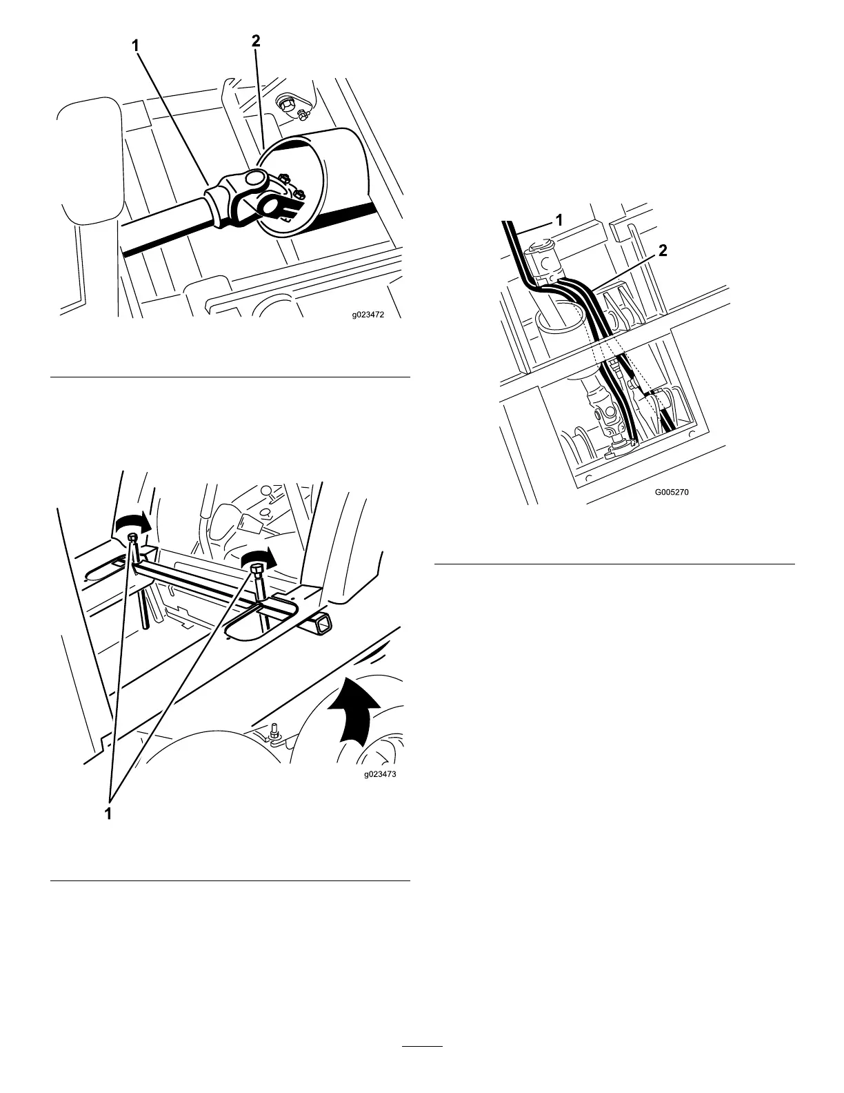
Figure17
1.Driveshaft
2.Frametube
Note:Iftherearofthecabisnothighenoughtoclear
thecontrolhandles,evenlytightenthejackingbolts
oneachsideofthecabjacktubetoraisetherearof
thecab(Figure18).
Figure18
1.Jackingbolts
5.Routethehosesasfollows:
A.Routethetankhoseundertheliftcylinderand
betweenthecylinder-mountingbracketstothe
valve(Figure19).
B.RoutethepressurehosealongsidethePTOshaft
tothevalve(Figure19).
Note:Toemphasizethehoserouting,thehoses
areshownwithoutthehosecoversinstalled.
Figure19
1.Tankhose2.Pressurehose
6.Connectthedriveshafttothegear-boxshaftinthe
winterframe,andtorquethebolts(5/16inch)to175
to225inch-lbs(20to25N-m).
7.Installtherollpin(Figure20).
21
 Loading...

