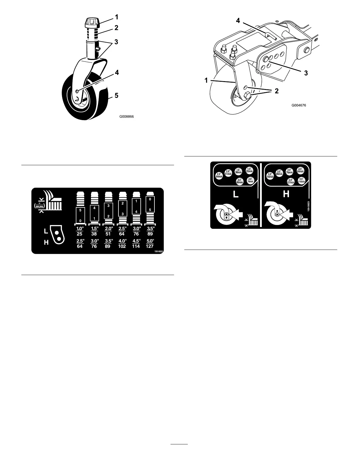
g008866
Figure22
1.Tensioningcap4.Toaxlemountinghole
2.Spacers5.Castorwheel
3.Shims
Refertothefollowingcharttodeterminethe
combinationsofspacersforthesetting.
decal100-5622nc
Figure23
3.Pushthecastorspindlethroughthecastorarm.
Installtheshims(asoriginallyinstalled)andthe
remainingspacersontothespindleshaft.Install
thetensioningcaptosecuretheassembly.
4.Removethehairpincotterandclevispinsfrom
thecastorpivotarms(Figure24).
5.Rotatetensionrodtoraiseorlowerpivotarm
untilholesarealignedwithselectedheight-of-cut
bracketholesinthecuttingunitframe(Figure
24andFigure25).
6.Inserttheclevispinsandinstallthehairpin
cotters.
7.Rotatetensionrodcounterclockwise(nger
tight)toputtensiononadjustment.
g004676
Figure24
1.Castorpivotarm3.Clevispinandhairpin
cotter
2.Axlemountingholes4.Tensionrod
decal100-5623nc
Figure25
AdjustingtheSkids
Theskidsshouldbemountedinthelowerposition
whenoperatingatheightsofcutgreaterthan64
mm(2-1/2inches)andinthehigherpositionwhen
operatingatheightsofcutlowerthan64mm(2-1/2
inches).
Adjusttheskidsbyremovingtheangeboltand
nuts,positioningthemasdesired,andinstallingthe
fasteners(Figure24).
31