movingpartstostop,removekey,andengage
parkingbrake.
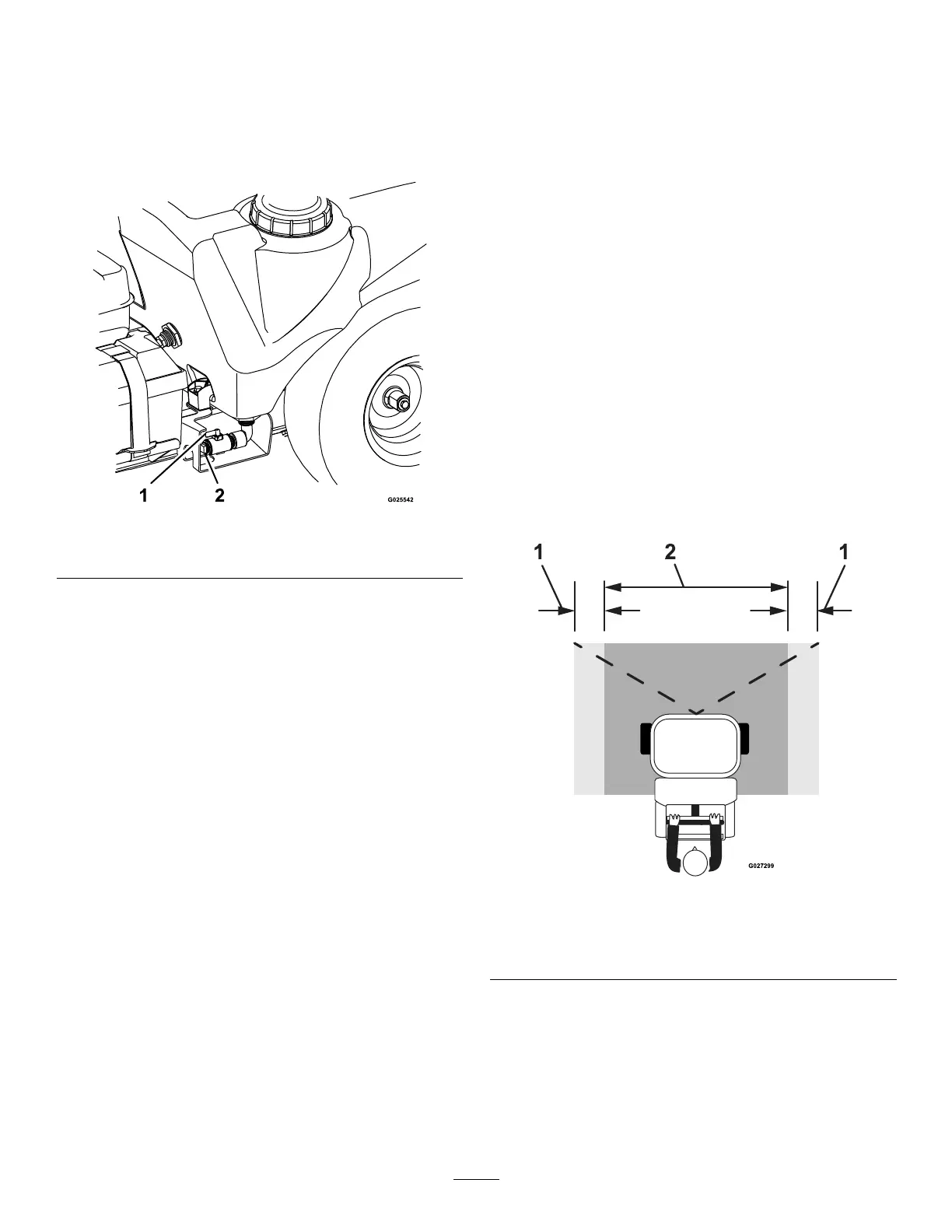
2.Removetheplugfromthedrainvalveforthe
sprayertank(Figure55).
Note:Thedrainvalveislocatedattheleftside
ofthemachine.
g025542
Figure55
1.Drainvalve2.Plug
3.Threadadrainhose(operatorprovided)intothe
endofthedrainvalve.
4.Putthefreeendofthedrainhoseintoa
containerwithenoughcapacitytoholdthe
remainingcontentofthesprayertank.
Note:Usethequantitymarksatthefront,
leftsideofthesprayertankfordeterminethe
quantityofchemicalsolutioninthetank.
5.Rotatethehandleforthedrainvalveclockwise
90°todrainthetank(Figure55).
Allowthesprayertanktodraincompletely.
6.ApplyPTFEthreadsealanttothethreadsofthe
plug.
7.Closethetank-drainvalve,removethedrain
hose,andinstallthedrainplugintothevalve
(Figure55).
Note:Disposeofthesprayerchemicals
accordingtolocalcodesandthechemical
manufacturer'sinstructions.
SprayingwiththeSprayerBoom
Important:Toensurethatyourchemical
solutionremainswellmixed,usetheagitation
featurewheneveryouhavesolutioninthe
tank.Fortheagitationfeaturetowork,setthe
sprayer-pumpswitchtotheONposition,pullback
thetank-agitationlever,andruntheengineathigh
idle.Ifyoushutoffthemachineandagitation
isneeded,leavethemotion-controlleverinthe
NEUTRALposition,engagetheparkingbrake,
increasethethrottletotheFASTposition,startthe
sprayerpumpandruntankagitation.
Note:Calibratethesprayerbeforeyoustartthespray
application;refertoCalibratingtheSprayer(page39).
1.Tapthesprayer-pumpswitchtotheONposition.
2.Drivethemachinetothejobsite.
3.Pushthetank-agitationlevertotheOFFposition.
Note:Thereissomeagitationeffectevenwhile
thetank-agitationleverisintheOFFposition.
4.Usethesprayer-pumpswitchtoadjustthespray
pressuretothesettingthatyoudeterminedin
NozzleApplicationRateT ables(page42).
5.Movethenarroworwide-spraypatternleverto
theONpositionandbeginspraying.
Important:Donotuseboththenarrowand
widecontrolsatthesametime.
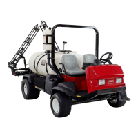
g027299
Figure56
Narrow-spraypattern
1.Overlaparea2.Effectivesprayarea
46