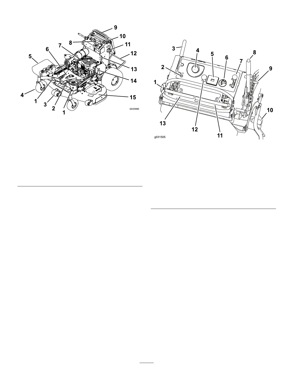
ProductOverview
Figure4
1.Adjustablecaster
9.Controllevers
2.Accessory-framelock
10.Hydraulictank
3.Anti-scalproller(60-inch
decksonly)
11.Fueltank
4.Frontcasterwheel
12.Platform(downposition)
5.Side-dischargechute13.Fuel-shutoffvalve
6.Accessoryframe
14.Battery
7.Engine15.Mowerdeck
8.Controls
Controls
Becomefamiliarwithallthecontrolsbeforeyoustartthe
engineandoperatethemachine(Figure5).
Figure5
1.Fuelcap
8.Height-of-cutlever
2.Malfunction-indicatorlight
(MIL)
9.Height-of-cutpin
3.Parking-brakelever
10.Platformlatch
4.Hydraulic-tankcap11.Rightmotion-controllever
5.Hourmeter12.Blade-controlswitch
(PTO)
6.Ignitionswitch
13.Leftmotion-controllever
7.Throttlecontrol
Electronic-ControlUnit
Malfunction-IndicatorLight
Theelectronic-controlunit(ECU)continuouslymonitorsthe
operationoftheEFIsystem.
Ifaproblemorfaultwithinthesystemisdetected,the
malfunction-indicatorlight(MIL)isilluminated(Figure5).
TheMIListheredlightlocatedintheconsolepanel.
WhentheMILilluminates,makeinitialtroubleshooting
checks.
Ifthesechecksdonotcorrecttheproblem,furtherdiagnosis
andservicingbyanAuthorizedServiceDealerisnecessary.
HourMeter
Thehourmeterrecordsthenumberofhourstheenginehas
operated.Itoperateswhentheengineisrunning.Usethese
timesforschedulingregularmaintenance(Figure5).
12