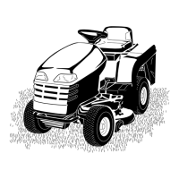
Figure77
1.Cuttingedge3.Wear/slotforming
2.Curvedarea4.Crack
CheckingforBentBlades
1.DisengagethePTO,movethemotion-controlleversto
theNEUTRAL-LOCKposition,andsettheparkingbrake.
2.Shutofftheengine,removethekey,andwaitforall
movingpartstostopbeforeleavingtheoperating
position.
3.Rotatethebladesuntiltheendsfaceforwardand
backward.
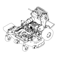
4.Measurefromalevelsurfacetothecuttingedge,
positionA,oftheblades(Figure78).
Figure78
1.Measureherefromblade
tohardsurface
2.PositionA
5.Rotatetheoppositeendsofthebladesforward.
6.Measurefromalevelsurfacetothecuttingedgeofthe
bladesatthesamepositionasinstep4above.
Note:Thedifferencebetweenthedimensions
obtainedinsteps4and5mustnotexceed3mm
(1/8inch).
Note:Ifthisdimensionexceeds3mm(1/8inch),
replacetheblade.
WARNING
Abladethatisbentordamagedcould
breakapartandcouldcriticallyinjureyouor
bystanders.
•Alwaysreplaceabentordamagedblade
withanewblade.
•Donotleorcreatesharpnotchesinthe
edgesorsurfacesoftheblade.
RemovingtheBlades
Replacethebladesiftheyhitasolidobject,ifabladeisoutof
balance,orifabladeisbent.Toensureoptimumperformance
andcontinuedsafetyconformanceofthemachine,use
genuineTororeplacementblades.Replacementbladesmade
byothermanufacturersmayresultinnonconformancewith
safetystandards.
1.Holdthebladeendusingaragorathickly-padded
glove.
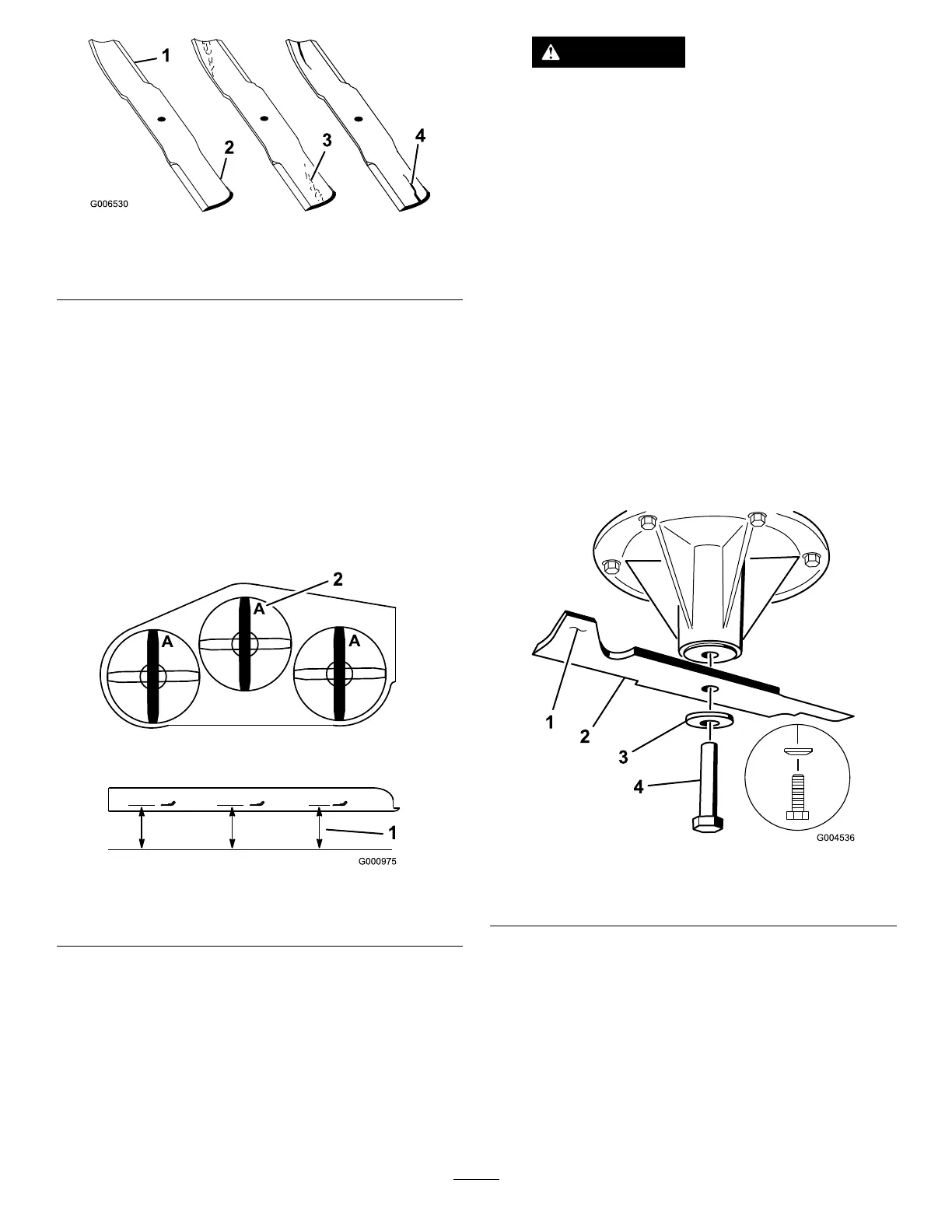
2.Removethebladebolt,thecurvedwasher,andthe
bladefromthespindleshaft(Figure79).
Figure79
1.Sailareaoftheblade3.Curvedwasher
2.Blade4.Bladebolt
51