ControlsSystem
Maintenance
AdjustingtheControl-Handle
Position
Thereare2heightpositionsforthecontrollevers—HIGH
andLOW.Removetheboltstoadjusttheheightforthe
operator.
1.DisengagethePTO,movethemotion-controlleversto
theNEUTRAL-LOCKposition,andsettheparkingbrake.
2.Stoptheengine,removethekey,andwaitforallmoving
partstostopbeforeleavingtheoperatingposition.
3.Loosentheboltsandangenutsinstalledinthelevers
(Figure79).
4.Aligntheleversfront-to-rearpositionbybringthe
leverstogethertotheNEUTRALpositionandslidethem
untiltheyarealigned,thentightenthebolts(Figure80).
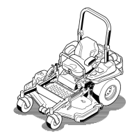
Figure79
1.Bolt
3.Controllever
2.Handle4.Nut
Figure80
AdjustingtheMotion-Control
Linkage
Locatedoneithersideofthefueltank,belowtheseatare
thepump-controllinkages.Rotatingthepumplinkagewith
a1/2–inchwrenchallowsne-tuningadjustmentssothat
themachinedoesnotmoveintoNEUTRALposition.Any
adjustmentsshouldbemadeforneutralpositioningonly.
WARNING
Enginemustberunninganddrivewheelsmust
beturningsoamotion-controladjustmentcan
beperformed.Contactwithmovingpartsorhot
surfacesmaycausepersonalinjury.
Keepngers,hands,andclothingclearofrotating
componentsandhotsurfaces.
1.Priortostartingtheengine,pushthedeck-liftpedal
andremovetheheight-of-cutpin.
2.Lowerthedecktotheground.
3.Raisetherearofmachineupandsupportwithjack
stands(orequivalentsupport).
Note:Raisethemachinejusthighenoughtoallow
drivewheelstoturnfreely.
4.Removetheelectricalconnectionfromtheseatsafety
switch,locatedunderthebottomcushionoftheseat.
Note:Theswitchisapartoftheseatassembly.
5.Temporarilyinstallajumperwireacrosstheterminals
intheconnectorofthemainwiringharness.
6.Starttheengine,runitatfullthrottle,andreleasethe
brake.
51