HX7+ ASD Installation and Operation Manual 35
CN7 Pinout
Listed below are the pinouts of the CN7 connector. The CN7 connector is the 25-pin D-type connector
of the Control Board (see
Figure 9 on pg. 33).
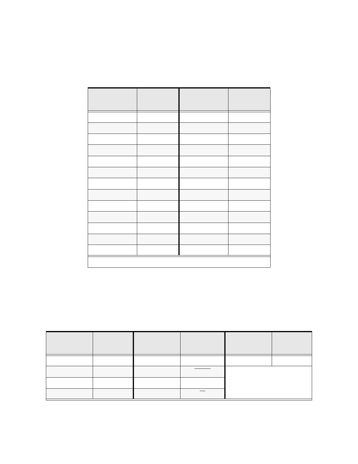
Table 9. CN7 pinout assignments. Default settings listed for the programmable terminals.
CN8 Pinout
Listed below are the pinouts of the CN8 connector. The CN8 connector is the 9-pin single in-line board-
edge connector of the Control Board (see
Figure 9 on pg. 33). The CN8 Option selection may be
chosen as the control input at the Frequency, Command, and Torque selections.
Table 10. CN8 pinout assignments.
Pin Number
CN7
Pinout
Pin Number
CN7
Pinout
1 PP 14 II
2 FL 15 S1
3 VI 16 R
4 RR 17 S3
5 FM 18 S2
6 RX 19 N15
7 FP 20 S4
8 AM 21 P15
9 *OUT1 22 P24
10 *OUT2 23 CC
11 ST 24 CC
12 RES 25 CC
13 F — —
Note: * Open collector outputs.
Pin Number
CN8
Pinout
Pin Number
CN8
Pinout
Pin Number
CN8
Pinout
1 GND 5 OUTLOAD 9 GND
2 MON 6 RESET
3 ENTER 7 IOCLK
4 OUTDAT 8 P5

 Loading...


