Chapter 2 Installing/Uninstalling
6F8C1575
28
2.4 Installing the Base Unit
Pay attention to the following items to install the base unit. For installing the base unit for
TC-net I/O, refer to “TC-net I/O Instruction Manual” (6F8C1240). For installing the
intelligent I/O, refer to “Intelligent PI/O Instruction Manual” (6F8C0779).
■
Precautions for installing the base unit for type2 light controllers
(1)
The controller unit is not dust-proof. Store it in the control board that takes
dust-proof into consideration as much as possible.
(2)
Avoid installing it directly above devices that generate lots of heat (such as heater,
transformer and large capacity resistor).
(3)
Do not install it on the same board as the high-voltage devices.
(4)
Put it off the high-voltage wire and the power wire at least 200mm.
(5)
Reserve at least 70mm space for ventilation around the base unit and the fan unit.
(6)
Place the type2 light controller as far from the high-voltage and power equipment
as possible, or provide an iron plate in between for isolation.
(7)
Install the base unit and the fan unit on the vertical panel surface.
(8)
Use four of M4 screws to install the base unit and the fan unit firmly (rough
indication of tightening torque: 1.47N
・
m=15kgf
・
cm).
(9)
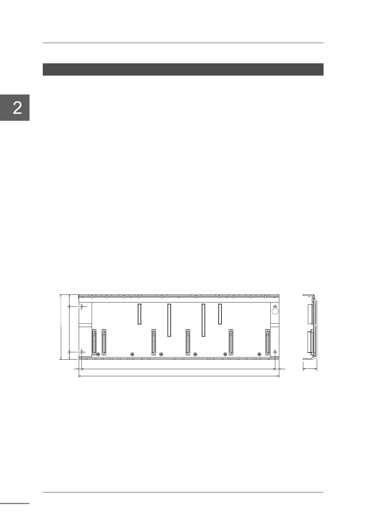
The dimension to install the base unit is shown in the following figure.
402.5
416.5
6
1 5 9 5
1 3 5
8
2 5
2 9
Figure 2-3
Dimension to install the base unit

 Loading...


