17
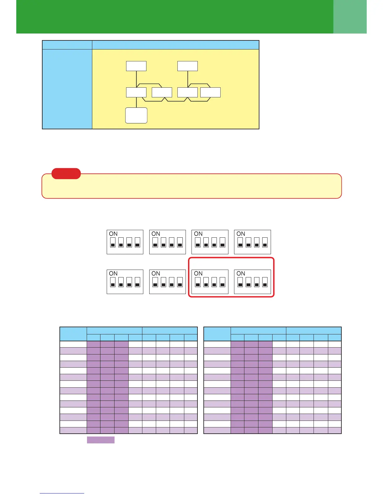
Address Setup
Address setting procedure 2
1 Set a system address for each system using SW 13 and 14 on the interface P.C. board on the header
outdoor unit of each system.
(Factory default: Address 1)
NOTE
Be sure to set a unique address on each system. Do not use a same address as another system (refrigerant
line) or “Digital Inverter” side.
Interface P.C. board on the header outdoor unit
(Example) Controlling 2 or more refrigerant lines as a group
System wiring
diagram
Outdoor
Indoor
Indoor
Indoor
Indoor
Outdoor
Remote
controller
(Group control)
SW06 SW07 SW09 SW10
SW11 SW12 SW13 SW14
1 2 3 4 1 2 3 4 1 2 3 4 1 2 3 4
1 2 3 4 1 2 3 4 1 2 3 4 1 2 3 4
Line address switches on the outdoor interface PC board (
O
: switch on, × : switch off)
SW13 SW14
1
1
2
3
4
5
6
7
8
9
10
11
12
13
14
×
×
×
×
×
×
×
×
×
×
×
×
×
×
×
O
×
O
×
O
×
O
×
O
×
O
×
O
×
×
O
O
×
×
O
O
×
×
O
O
×
×
×
×
×
×
O
O
O
O
×
×
×
×
O
O
×
×
×
×
×
×
×
×
O
O
O
O
O
O
2 3 4 1 2 3 4
SW13 SW14
1
15
16
17
18
19
20
21
22
23
24
25
26
27
28
×
×
O
O
O
O
O
O
O
O
O
O
O
O
×
O
×
O
×
O
×
O
×
O
×
O
×
O
O
O
×
×
O
O
×
×
O
O
×
×
O
O
O
O
×
×
×
×
O
O
O
O
×
×
×
×
O
O
×
×
×
×
×
×
×
×
O
O
O
O
2 3 4 1 2 3 4
Not used for setup of line address (do not change setup.)
Line
address
Line
address