19
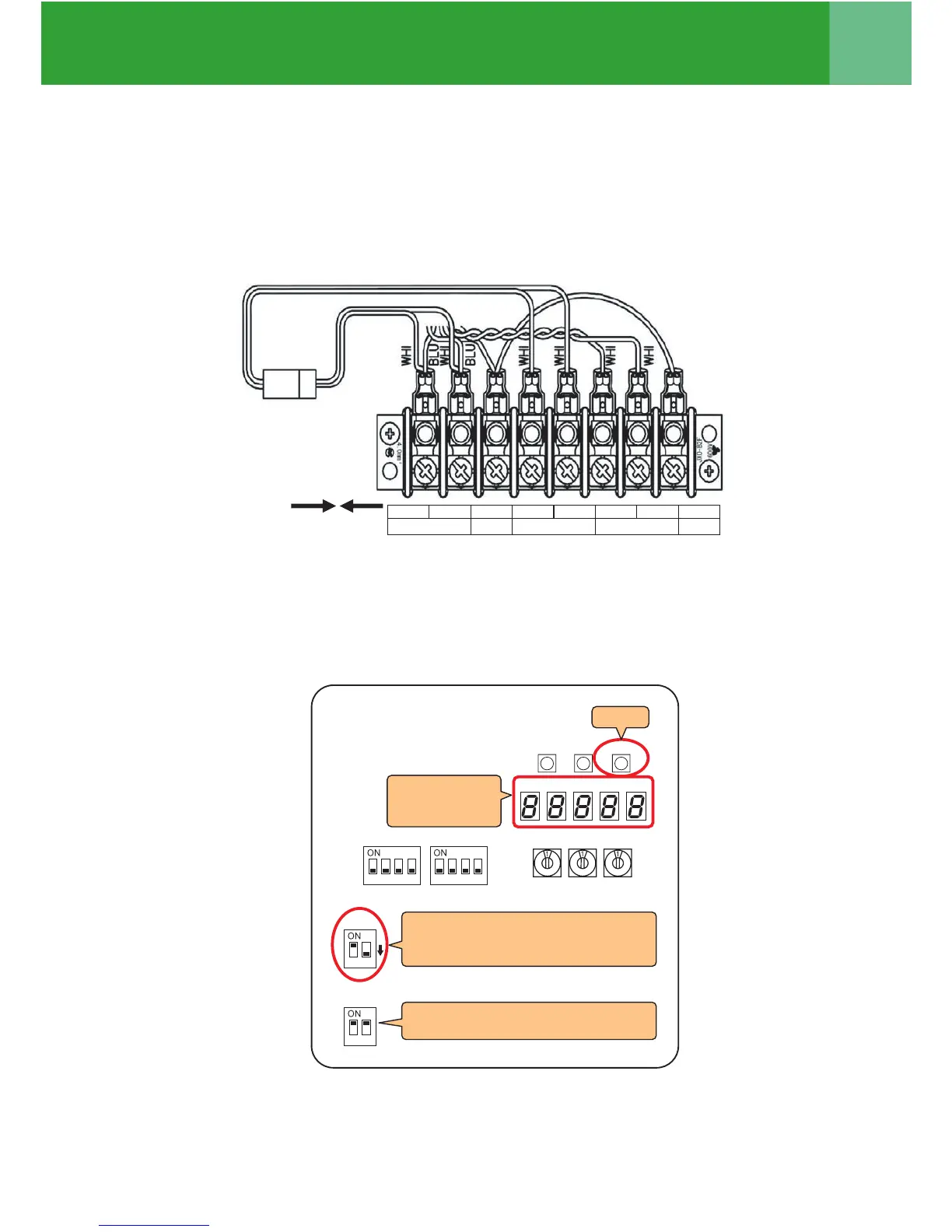
Address Setup
10 Set the central control address.
(For the setting of the central control address, refer to the installation manuals of the central control devices or
“Manual address setup from the remote controller” in the next to the following page and after.
SW15
SW04
1 2
SW13
SW30
SW14
SW01 SW02
SW03
D600 D601 D602 D603 D604
SW05
7-segment
display
Header unit interface P.C. board
SW30 bit 2 switch OFF
* Except the smallest line address of
header unit
8
1 2
SW30
SW30 bit switch ON
* The smallest line adress of header unit
4, 6
5
8 After completing address setting of all systems, turn off DIP switch 2 of SW30 on the interface P.C.
boards of all the header outdoor units connected to the same central control, except the unit that has
the lowest address.
(For unifying the termination of the wiring for the central control of indoor and outdoor units)
9 Connect the relay connectors between the [U1, U2] and [U3, U4] terminals of the header outdoor unit of
each refrigerant line.
9
U1 U2 S U3 U4 U5 U6 S
DLEIHSDLEIHS
TO CENTRAL CONTROLLER TO OUTDOOR UNITTO INDOOR UNIT