STE 80897
– 3–10 –
TRANSPORTATION & INSTALLATION MANUAL
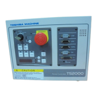
3.3.2 Cable between Controller and Control Panel
The cable required to connect the control panel and controller when they are installed
separately can be provided optionally.
3.3.3 Control Panel Mounting Dimensions
The dimensions of mounting the control panel are shown in Fig. 3.5.
Cross truss head screws (ø3×6, ZN3–B) are used.
RUN
STOP
CYCLE
SELECT
UF1
UF2
ALARM
SERVO
ON
SERVO
OFF
LINE
USER
ALAR M
EMERGENCY
RESE T
MODE
POWER
EXT.SIGNAL
EXT.HOS T
INTERNAL
TEACHING
EXT
5 125 5
135
5 125 5
135
(M3 pitch)
(M3 pitch)
Fig. 3.5 Control panel mounting dimensions

 Loading...