STE 80897
– 3–9 –
TRANSPORTATION & INSTALLATION MANUAL
3.3 Separating Control Panel from Controller
3.3.1 Removing Control Panel
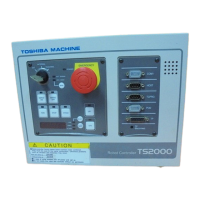
Remove the control panel in the following manner.
a) Loosen the four (4) screws at the four (4) corners, which secure the control panel.
b) Remove these screws, then carefully draw out the control panel toward your side.
(Be careful of the cable connected on the rear side.)
50/60Hz
2φ
AC I N
<コントローラ側>
コネクタ(AC IN)の電源線とア-ス線の
接続は必ず下図の配線にしてください。
誤配線すると、感電や機器破損の原因と
なります。
注 意
感電により死傷の恐れが あ
ります。
保守・点検作業の前に必 ず
電源を切り、コントロ- ラ
の電 源コ ネクタ (AC IN)を
はずしてください 。
警 告
AC180~ 250V
Fig. 3.4 Removing control panel
Controlle
Control panel

 Loading...