TRANSPORTATION AND INSTALLATION MANUAL
117
• NEVER operate the robot under the load conditions exceeding the
permissible values. Otherwise, the robot life and safety cannot be
guaranteed.
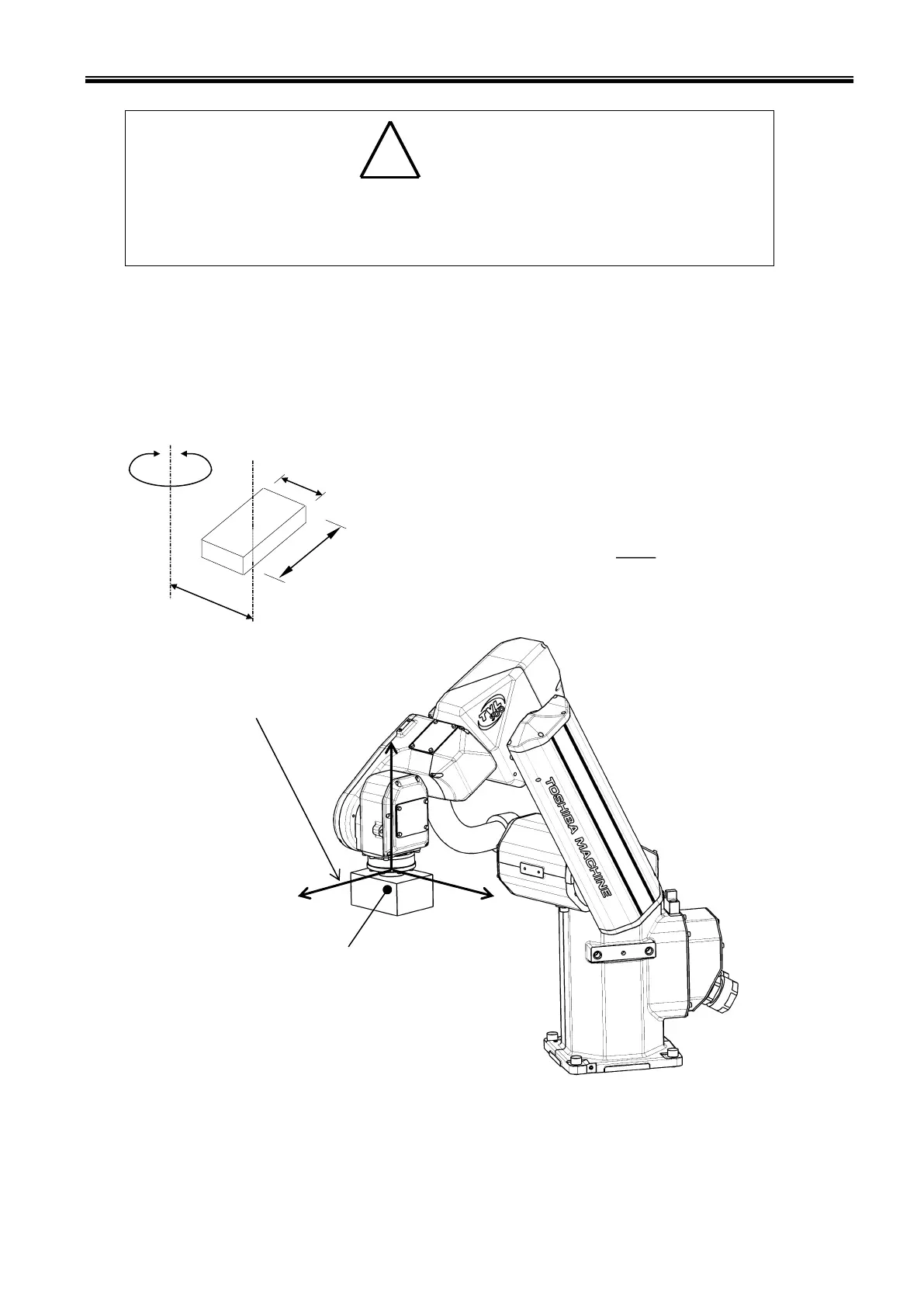
Inertia moment
The following drawing shows an example of a model with simplified robot and load,
and a formula for calculating the load inertia moment.
L : Distance from the center of axis 6 to load center
gravity (m)
a: Load width (m)
b: Load length (m)
M: Load mass (kg)
Inertia moment (kg•m
2
) = (a
2
+b
2
) + ML
2
Fig. 10.5 Robot tool coordinate system
coordinate system

 Loading...


